5
03.96
5.2 Power on and power-up
5-77
Siemens AG 2000 All Rights Reserved
SINUMERIK 840D Installation and Start-Up Guide (IAD) – 04.00 Edition
5.2 Power on and power-up
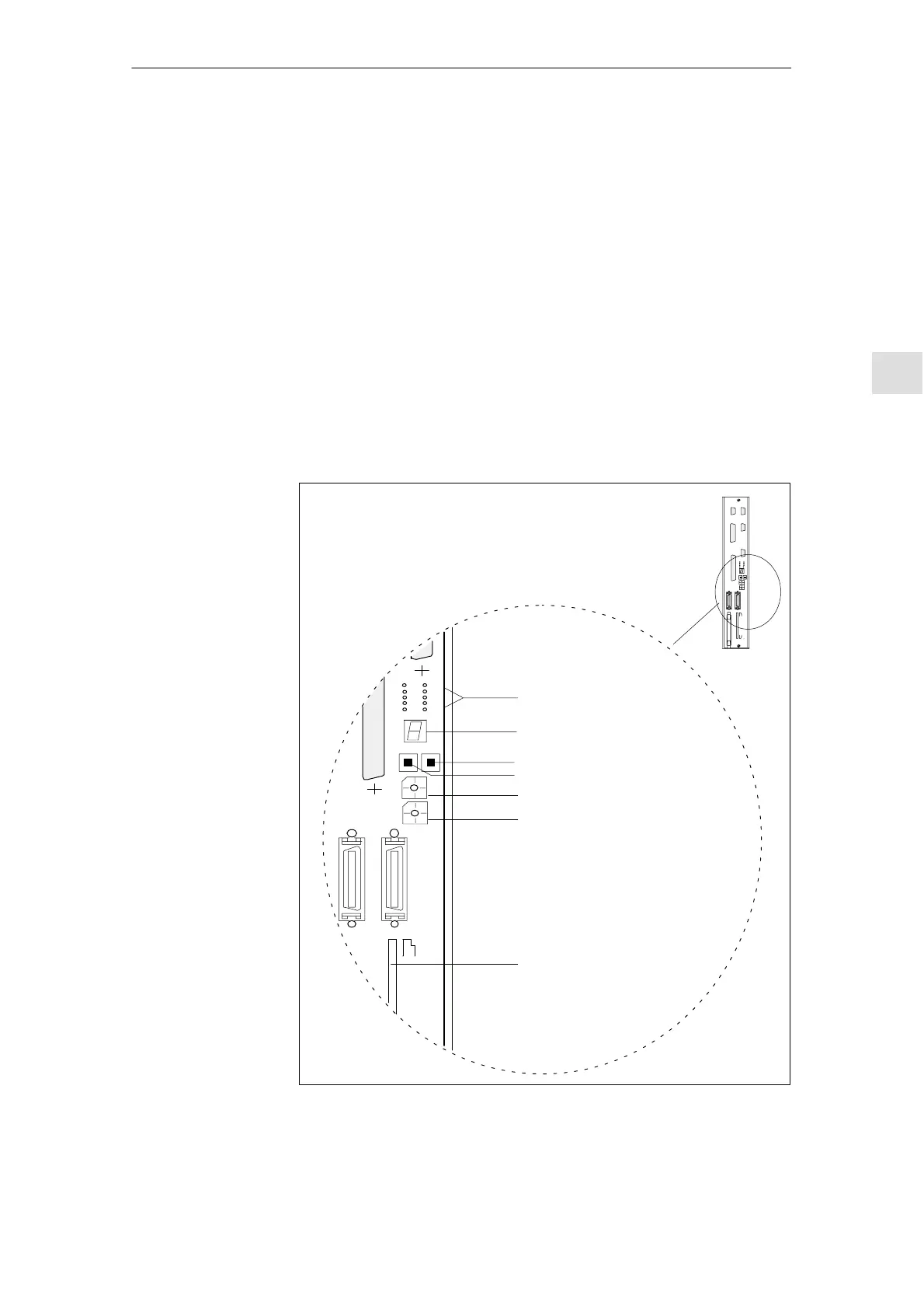
Fig. 5-1 below shows the operator control and display elements on the NCU
that are relevant for switching on and powering up the SINUMERIK 840D:
S Various error and status LEDs
S 7-segment status display
S NMI button
S RESET button
S NCK start-up switch
S PLC start-up switch
S PCMCIA slot
Various errors and status LEDs
Status display (H3)
RESET button (S1)
NMI button (S2)
PLC start-up switch (S4)
NCK start-up switch (S3)
PCMCIA slot
(X145)
MEMORY–CARD
X172
S3
X130B
X130A
S4
RESETNMI
+5V
NF
CF
CB
CP
PR
P
S
P
F
PF0
–
Fig. 5-1 Operator control and display elements of the NCU
Operator control
and display
elements relevant
to power-up
5 Power On and Power-Up

 Loading...


