2
03.96
2.2 Electrical configuration
2-25
Siemens AG 2000 All Rights Reserved
SINUMERIK 840D Installation and Start-Up Guide (IAD) – 04.00 Edition
Note
For cables and connectors, see
References: /PHD/, Configuring Manual 840D
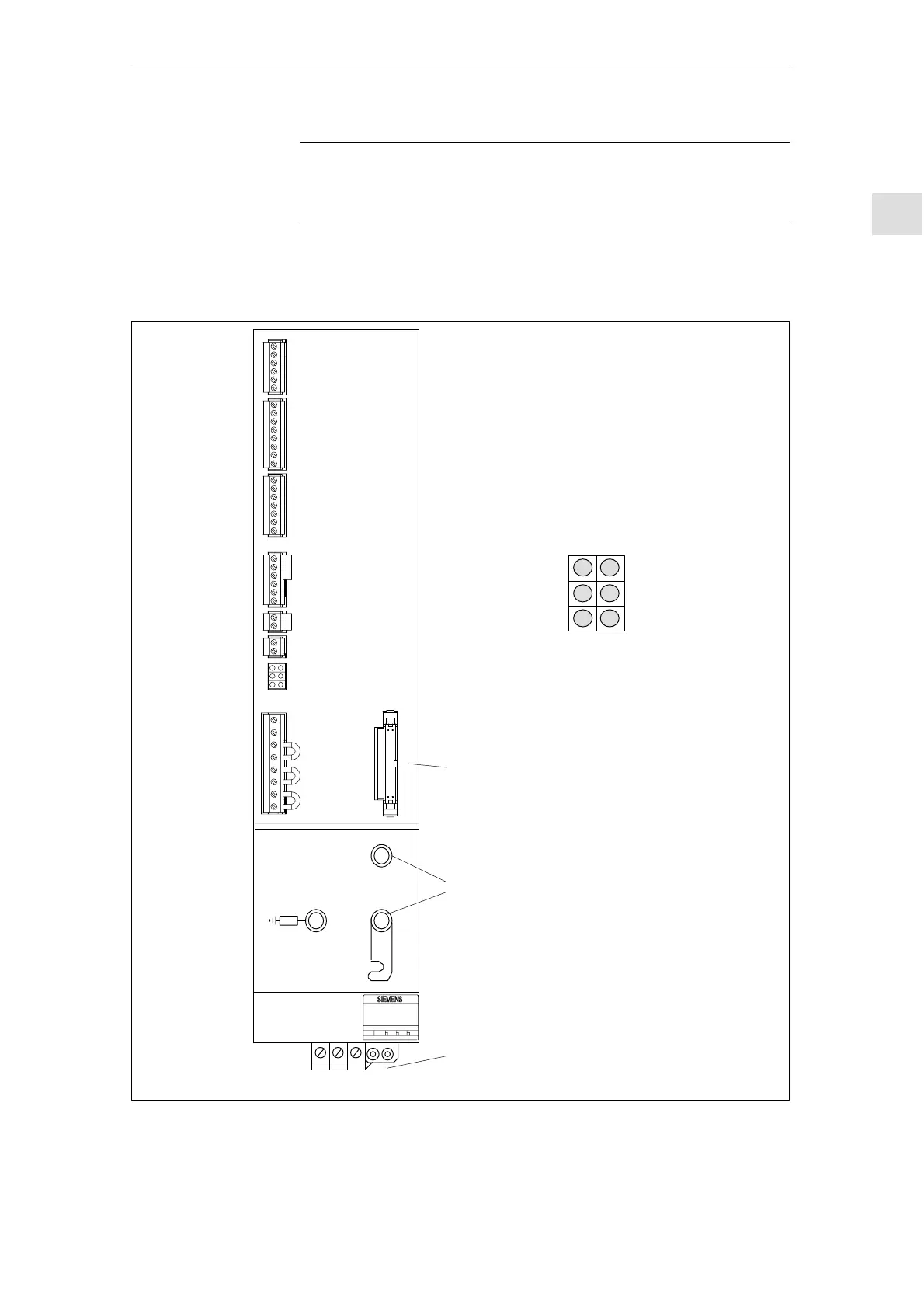
2.2.2 Connection of mains infeed module (OI, I/RF)
M600
P600
X351
X111
X121
X141
X161
X171
X172
X181
U1 V1 W1 PE1
Red
Yellow
Red
5V voltage
level faulty
Device ready
(DC link
precharged)
DC link over-
voltage
Electronics power
supply faulty
Device is not ready,
no enable signal
(term. 63, 64 or 48)
Mains fault
Power supply
Device bus
DC link connection
Red
Green
Red
LED
displays
LED displays
Fig. 2-5 Interfaces for OI and I/RF module 10–55KW
2 Confi
uration

 Loading...


