3
03.96
3.6 Machine control panel (MCP)
3-66
Siemens AG 2000 All Rights Reserved
SINUMERIK 840D Installation and Start-Up Guide (IAD) – 04.00 Edition
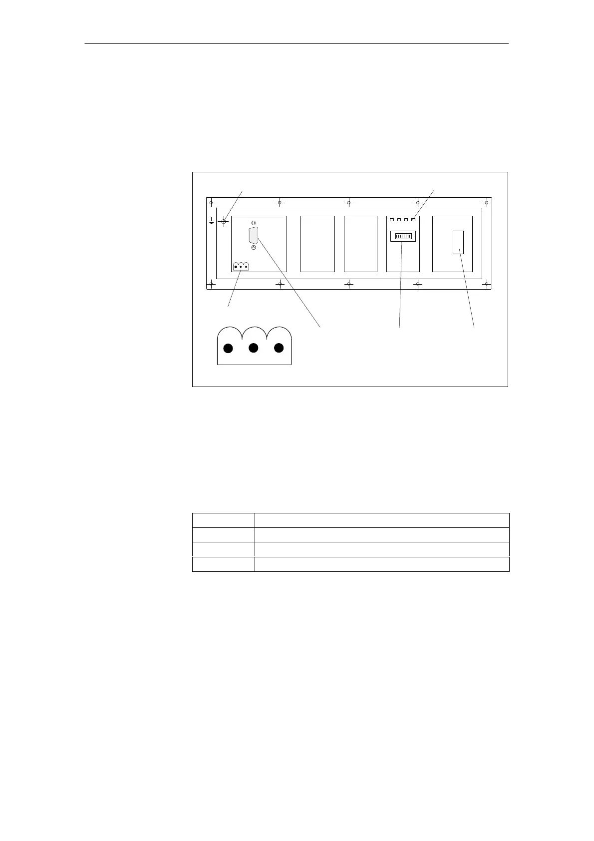
3.6 Machine control panel (MCP)
The following interfaces, switches and display elements are located on the rear
of the machine control panel:
Operator panel
interface (MPI)
Power supply interface
Switch S3
X10
X20
S3
31
42
Emergency
STOP button
ON
”
1234
LEDs 1...4
Connection for equipotential bonding conductor
12 3
SHIELD M24 P24
Fig. 3-11 Position of interfaces on rear panel of MCP
The interfaces (e.g. pin assignment) are described in detail in
References: /BH/, Operator Components Manual
Table 3-7 Meaning of LEDs 1...4 on rear panel of MCP
Designation Meaning
LEDs 1 and 2 Reserved
LED 3 POWER: Lights up when voltage (24 V) is present
LED 4 SEND: Changes state after transmission of data
If the “feed start” and “feed stop” keys are pressed while the MCP is powering
up, the software version is displayed in the left-hand, center and right-hand LED
blocks.
The module must have firmware version V 03_01_01 or higher.
Example After the software version display has been activated, 3/1/1 LEDs light up in the
left-hand/center/right-hand LED blocks.
––> SW version v03_01_01 is installed.
Interfaces,
switches and
display elements
Interfaces
LEDs 1...4
Display software
version of MCP
3 Settin
s, MPI / OPI
08.97

 Loading...


