3
03.96
3.4 Handheld unit
3-53
Siemens AG 2000 All Rights Reserved
SINUMERIK 840D Installation and Start-Up Guide (IAD) – 04.00 Edition
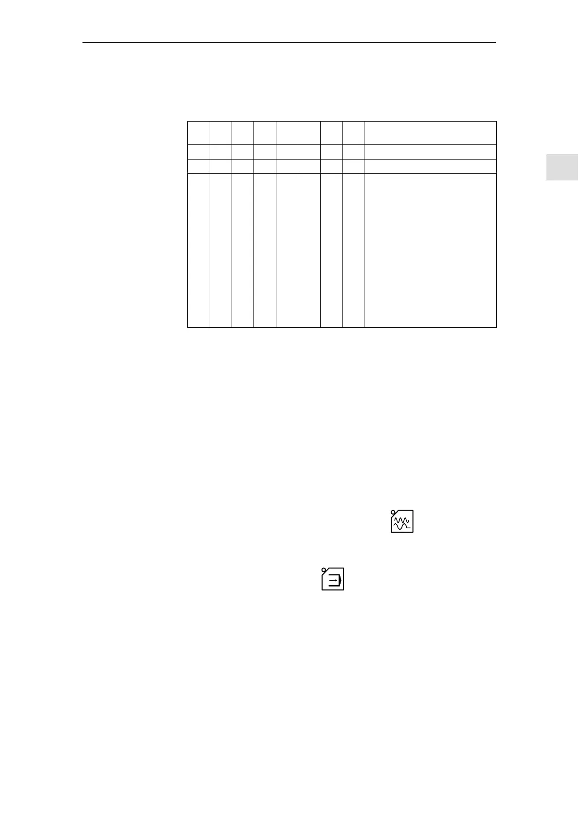
S1 “3” must be set to “on” when operating the HHU on the OPI.
Table 3-4 Settings on switches S1 and S2 in HHU
S1
1
S1
2
S1
3
S1
4
S2
1
S2
2
S2
3
S2
4
Meaning:
off on off off on on on on Default setting
on Baud rate: 1.5 Mbaud OPI
on
on
on
on
on
on
on
on
off
off
off
off
off
off
off
off
on
on
on
on
off
off
off
off
on
on
on
on
off
off
off
off
on
on
off
off
on
on
off
off
on
on
off
off
on
on
off
off
on
off
on
off
on
off
on
off
on
off
on
off
on
off
on
off
Bus address: 15
Bus address: 14
Bus address: 13
Bus address: 12
Bus address: 11
Bus address: 10
Bus address: 9
Bus address: 8
Bus address: 7
Bus address: 6
Bus address: 5
Bus address: 4
Bus address: 3
Bus address: 2
Bus address: 1
Bus address: 0
3.4.2 Settings on the HHU for software version 4.x and higher
The settings for “baud rate” and “bus address” parameters made with switches
S1 and S2 on the HHU no longer apply to software version 4.x and higher.
These bus parameters can be reconfigured from this software version
(cf. Section 3.4.3).
3.4.3 Configuring the HHU, setting interface parameters
The GD parameters must be set before the submodule can communicate via
the MPI interface. The setting can be activated during power-up (i.e. while wait-
ing for the first GD message frame from the PLC (“Waiting for PLC” state) via
the HHU interface by means of key combination Jog
(top far left) and T2
(top far right). The individual parameters are then interrogated via the HHU dis-
play and entered via the HHU keyboard. You can change the default values
with the + and – keys within the permitted value range. You can switch to the
next parameter with the Automatic
key. Selection of the next parameter
causes the preceding parameter to be stored in the Flash EPROM. The param-
eters need therefore only be set during start-up and when interfaces are
changed. If the interface parameter settings are not activated after power-up,
the stored values are used or the default values (see table) loaded.
DIP switch
settings for OPI
3 Settin
s, MPI / OPI
08.97

 Loading...


