6 Assi
nin
Parameters to the Control and the PLC Pro
ram
6
03.96
6.12 System settings for power up, RESET and part program start
6-177
Siemens AG 2000 All Rights Reserved
SINUMERIK 840D Installation and Start-Up Guide (IAD) – 04.00 Edition
6.12 System settings for power up, RESET and part program
start
The behavior of the control after
S Power up (POWER ON),
S Reset/part program end
S Part program start
can be changed with the machine data
MD 20110: RESET_MODE_MASK (definition of the control initial setting
after power up and reset) and
MD 20112: START_MODE_MASK (definition of the control initial setting
after part program start).
Table 6-25 Change system setting with MD
State Variable with MD
Power up (POWER ON) RESET_MODE_MASK
RESET/part program end RESET_MODE_MASK
Part program start START_MODE_MASK and
RESET_MODE_MASK
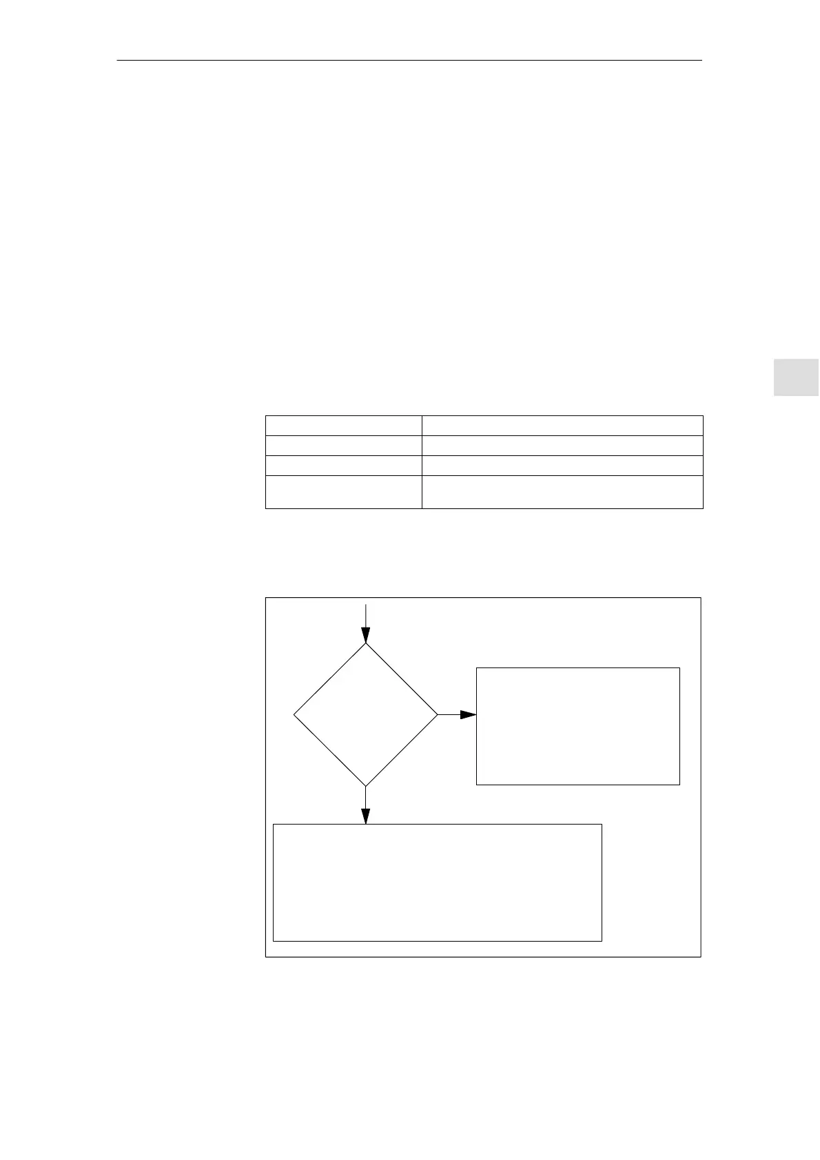
Select the required system behavior.
S After power up (POWER ON)
MD 20110: RESET_MODE_MASK, bit 0 = 0 or 1
Power up
(POWER ON)
MD 20110
RESET_MODE_MASK
bit 0
bit 0=0
bit 0=1
– G codes acc. to MD 20150: GCODE_
RESET_VALUES
– Tool length compensation not active
– Transformation not active
– No coupled-axis groupings active
– No tangential correction active
– not project. Synchronous spindle
coupling is deactivated
– G codes acc. to MD 20150: GCODE_RESET_VALUES
– Tool length compensation active to MD 20120: TOOL_RESET_
VALUE, MD 20121: TOOL_PRESEL_RESET_VALUE and
MD 20130: CUTTING_EDGE_RESET_VALUE
– Transformation active to MD 20140: TRAFO_RESET_VALUE
– No coupled-axis groupings active
– No tangential correction active
– Not project. synchronous spindle coupling is deactivated
Fig. 6-45 System settings after power-up
Concept
Procedure

 Loading...


