10
03.96
10.5 Frequency response measurement
10-213
Siemens AG 2000 All Rights Reserved
SINUMERIK 840D Installation and Start-Up Guide (IAD) – 04.00 Edition
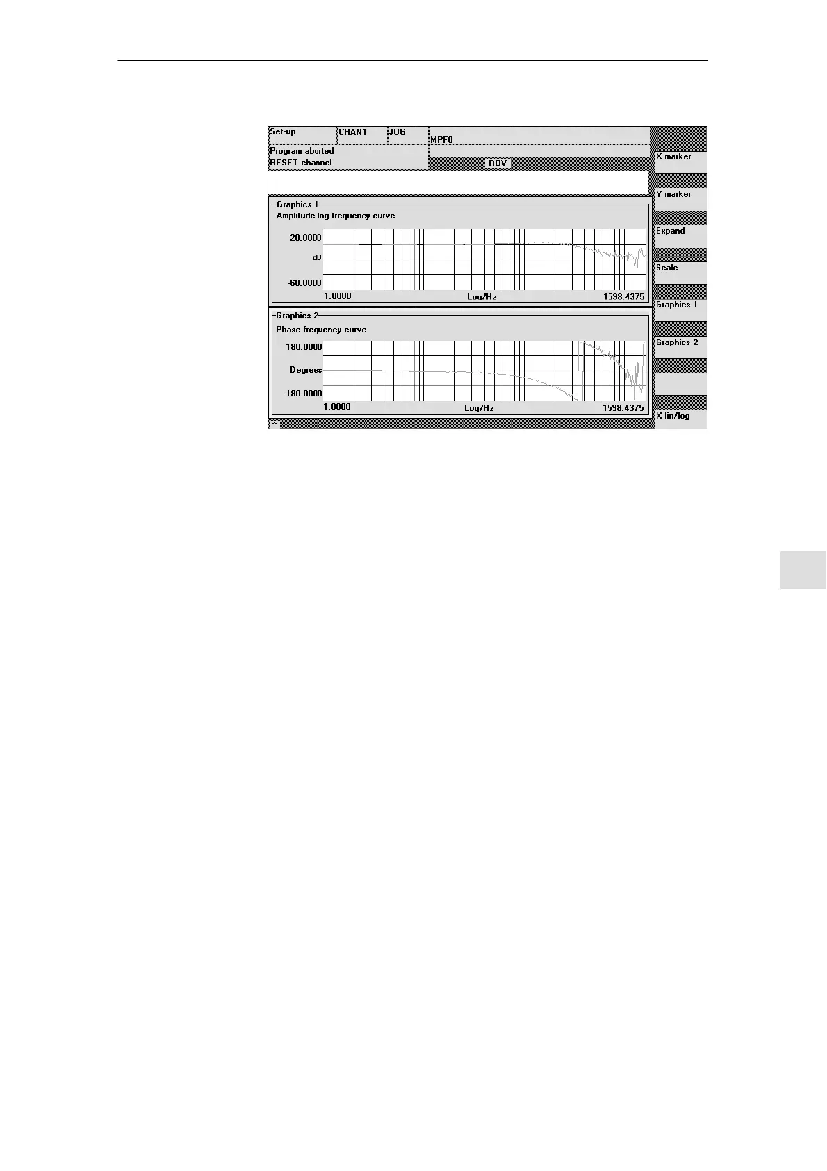
Fig. 10-2 Display diagram: Example of speed control loop
The frequency response measurement calculates the response of the speed
controller. The response range should be as wide as possible and without reso-
nance. It may be necessary to install stop or low-pass (611D) filters. Particular
care must be taken to prevent resonance within the speed controller limit fre-
quency range (stability limit approx. 200–500Hz).
Alternatively, the interference frequency response can be recorded in order to
assess how well the control suppresses interference.
Amplitude
This parameter determines the magnitude of the test signal amplitude. This
should give rise to only a very low speed of a few (approximately 1 to 2) revs/
min at the motor end.
Offset
The measurement requires a slight speed offset of a few motor revolutions per
minute. The offset must be set to a higher value than the amplitude.
SW 4.1 and higher:
S The Offset is run up via an acceleration ramp.
S The acceleration value is defined for one
axis: check MD 32300: MAX_AX_ACCEL
spindle: check MD 35200: GEAR_STEP_SPEEDCTRL_ACCEL
MD 35210: GEAR_STEP_POSCTRL_ACCEL
S The following applies:
Acceleration value = 0, no ramp
Acceleration value > 0, ramp active
S The actual measuring function is only activated when the offset value is
reached.
Reference
frequency
response
Interference
frequency
response
Measurement
parameters for
reference and
interference
frequency
response
10 Drive Optimization with Start-Up Tool
05.97

 Loading...


