2
03.96
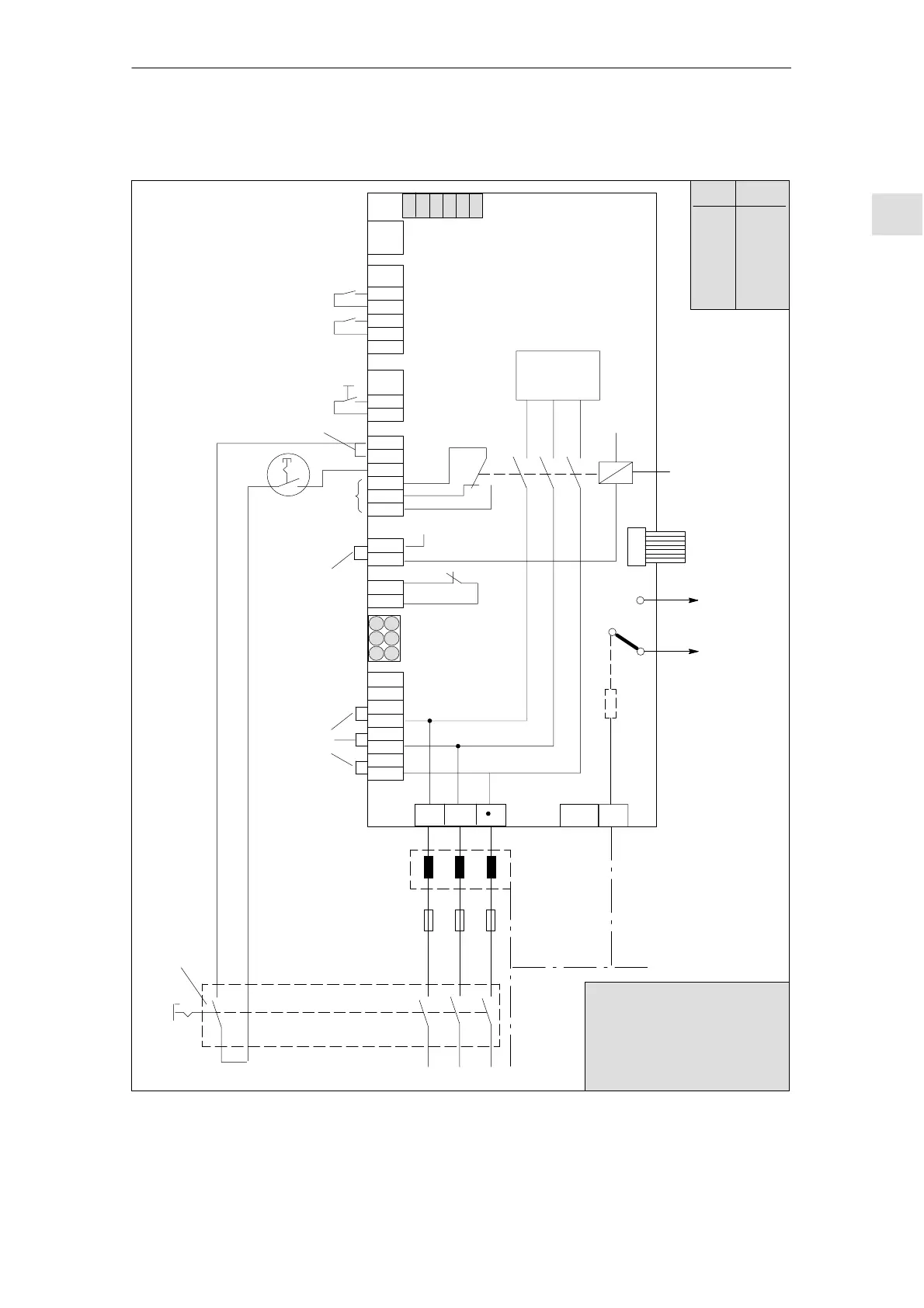
2.2 Electrical configuration
2-27
Siemens AG 2000 All Rights Reserved
SINUMERIK 840D Installation and Start-Up Guide (IAD) – 04.00 Edition
I/RF module
Mains supply module
X111
X121
P500
2U1
1U1
2V1
1V1
2W1
1W1
63
9
64
19
9
15
R
9
112
48
111
113
AS1
AS2
NS1
NS2
W1V1U1
X131
X351
PE
X141
X161
X171
X172
X181
Pushbutton contact
M500
213
S1.6
LEDs
P600
Device bus
100 k
L1 L2 L3
1U2 1V2 1W2
1U1 1W11V1
Commutating
reactor, on I/RF
module only
Mains fuses for
I/RF or OI
module
PE
Supply
P600
M600
M600
to the
axis modules
Master switch
Leading
contact
Power section
L–
Internal mains
contactor
1)
Important!
Terminal 48 must be de-ener-
gized 10 ms before the mains
contacts of the master switch
open (e.g. by means of leading
contact)
S1.5
S1.4
S1.3
S1.2
S1.1
L+
S1–DIP switch
1)
1)
1) Jumpers inserted in
delivery state
S1 Default
S1.1
S1.2
S1.3
S1.4
S1.5
S1.6
off
off
off*
off*
*Do not alter
off
off
Fig. 2-7 Example of three-conductor connection (standard circuit)
Typical circuit
2 Confi
uration

 Loading...


