3
03.96
3.3 Connection of a 2nd MCP/customer OPI and/or 1 HHU (up to SW 3.1)
3-49
Siemens AG 2000 All Rights Reserved
SINUMERIK 840D Installation and Start-Up Guide (IAD) – 04.00 Edition
You can now make the entries for the HHU in table 1.
1. Start in column as314//CPU1:: by selecting the first field.
2. Enter data area for reception or transmission from Fig. 3-6.
For bhg//CPU1::
mb0 : 20 is the receive area and
mb20 : 6 is the entry for the transmit area.
(mb0 : 20 means that 20 bytes are received starting at mb0 and
mb20 : 6 means that 6 bytes are transmitted starting at mb20.)
3. Declare the transmit and receive areas to be such. The transmit area is then
marked with “»”.
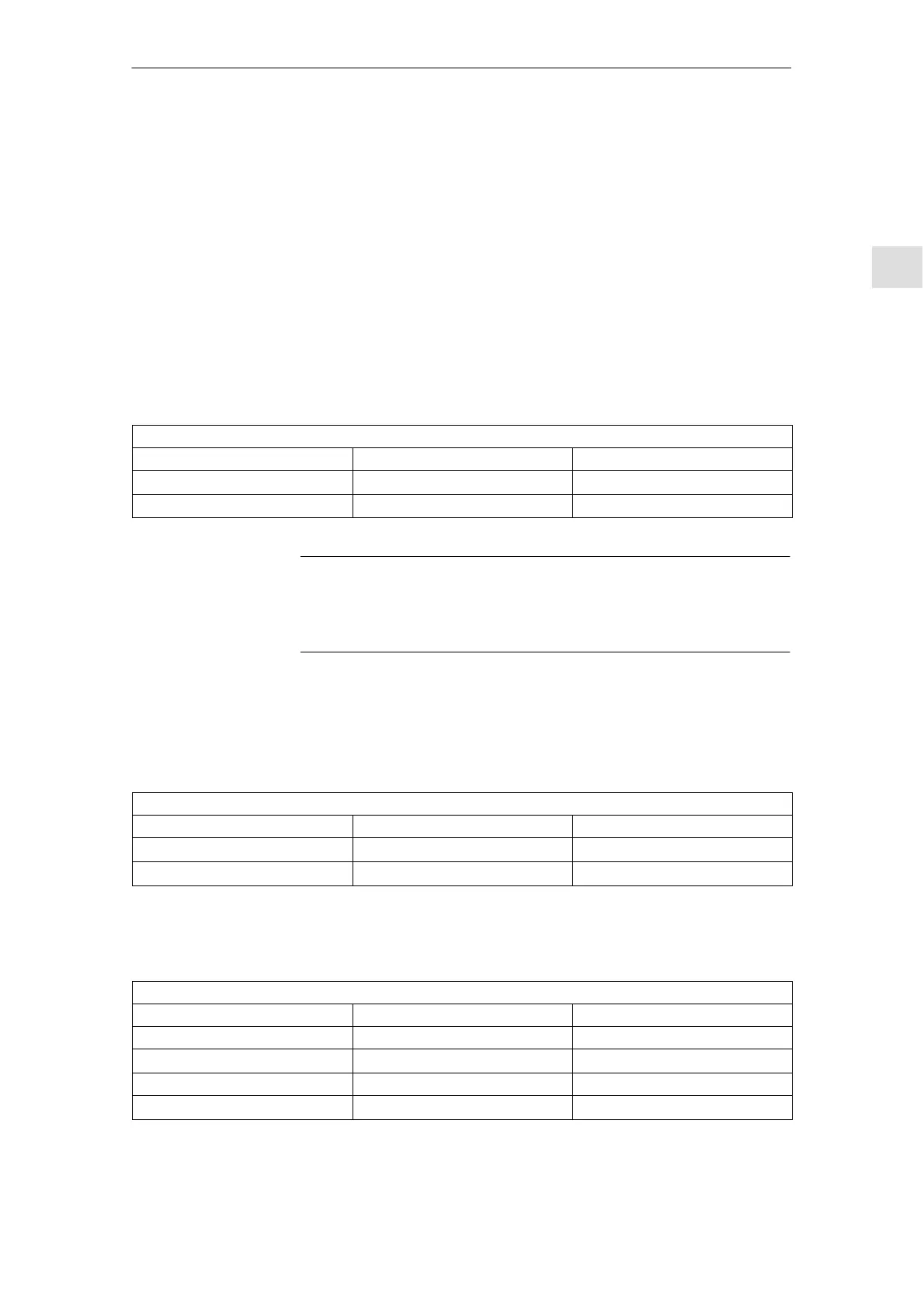
4. Table 1 with all its entries then looks like this:
table 1
GD identifiers as314//CPU1:: bhg//CPU1::
GD
»mb0:20
mb0:20
GD mb20:6
»mb20:6
Note
The order in which inputs are made (transmit, receive) affects the way in which
GD identifiers are assigned and should be carefully observed as shown by the
above example.
You now need to select compilation.
The GD identifiers are generated during compilation. The GD identifiers are dis-
played in Table 1 as the result of compilation.
table 1
GD identifiers as314//CPU1:: bhg//CPU1::
GD 1.1.1
»mb0:20
mb0:20
GD 1.2.1 mb20:6
»mb20:6
Click the View / Reduction ratio menu. Table 1 below appears with the SR pa-
rameters.
table 1
GD identifiers as314//CPU1:: bhg//CPU1::
SR 1.1 8 8
GD 1.1.1
»mb0:20
mb0:20
SR 1.2 8 8
GD 1.2.1 mb20:6
»mb20:6
Enter areas for
transmitting and
receiving
Compilation
Setting the
reduction ratio
3 Settin
s, MPI / OPI

 Loading...


