Detailed description
2.12 Block descriptions
Basic logic functions: PLC Basic program powerline (P3 pl)
Function Manual, 11/2006, 6FC5397-0BP10-2BA0
179
Description of formal parameters
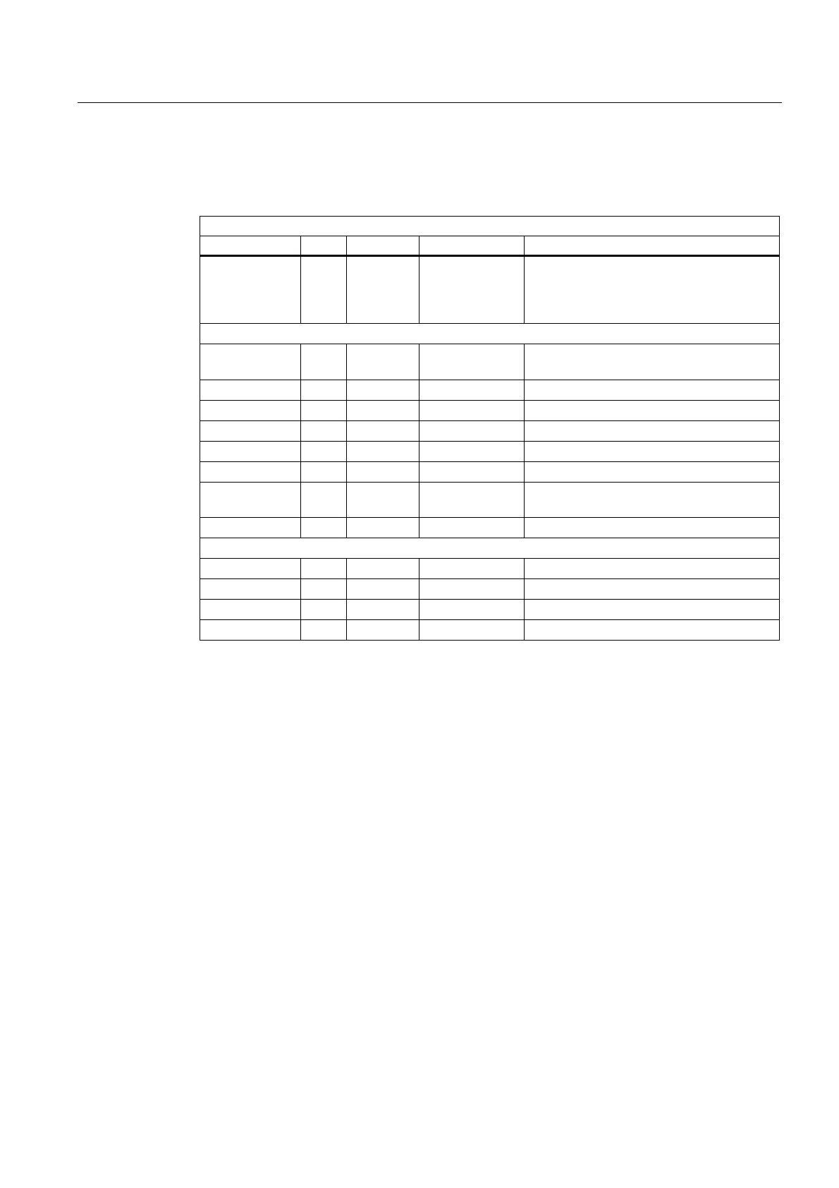
The table below lists all formal parameters of the Diagnostics function:
Formal parameters of diagnostics function
Signal Type Type Value range Remark
Func I INT 0, 1, 2 Function
0: Deactivate
1: Signal recorder
2: Data trigger
Parameters for function 1
Signal_1 to
Signal_8
I BOOL Bit signals checked for change
NewCycle I BOOL See the "Signal recorder" description above
Var1 I BYTE Additional value
Var2 I INT Additional value
VAR I INT Additional value
BufDB I INT Ring buffer DB no.
ClearBuf I BOOL Delete ring buffer DB and reset pointer
BufAddr
BufAddr I/O INT Target area for read data
Parameters for function 2
DataAdr I POINTER Pointer to word to be tested
TestVal I WORD Comparison value
AndMask I WORD See description
TestIsTrue A BOOL Result of comparison
Configuration steps
• Select function of diagnostics block.
• Define suitable data for the recording as signal recorder or data triggering.
• Find a suitable point or points in the user program for calling the diagnostics FB.
• Create a data block for the ring buffer, see call example.
• Call the diagnostics FB with parameters in the user program.
In function 1, it is advisable to clear the ring buffer with the "ClearBuf" parameter. When the
recording phase with function 1 is completed, read out the ring buffer DB in STEP7 with the
function "opening the data block in the data view". The content of the ring buffer DB can now
be analyzed.

 Loading...


