Detailed Description
2.7 Basic tool orientation
Basic logic functions: Tool Offset (W1)
128 Function Manual, 11/2006, 6FC5397-0BP10-2BA0
2.7 Basic tool orientation
Application
Normally, the orientation assigned to the tool itself depends exclusively on the active
machining plane. For example, the tool orientation is parallel to Z with G17, parallel to Y with
G18 and parallel to X with G19.
Different tool orientations can only be programmed by activating a 5axis transformation. The
following system variables have been introduced in order to assign a separate orientation to
each tool cutting edge:
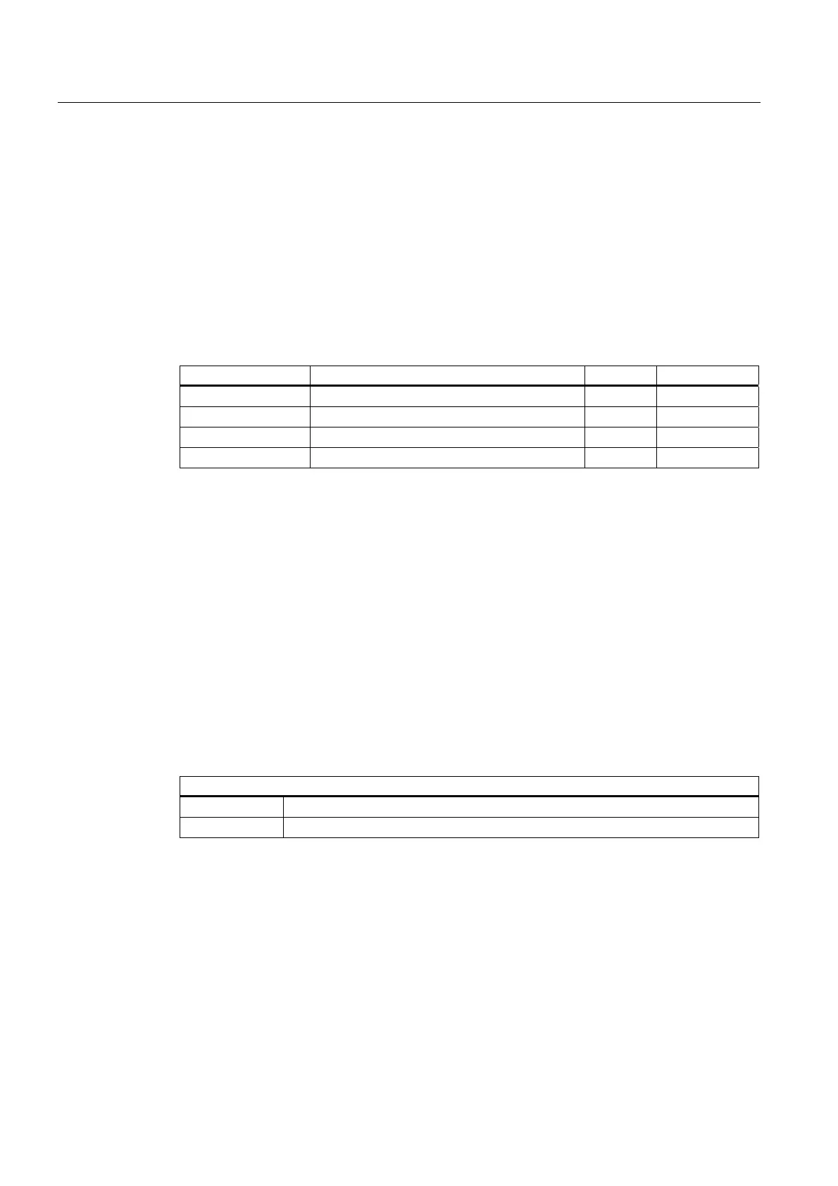
System variable Description of tool orientation Format Preassignment
$TC_DPV[t, d] Tool cutting edge orientation
INT
0
$TC_DPV3[t, d] L1 component of tool orientation
REAL
0
$TC_DPV4[t, d] L2 component of tool orientation
REAL
0
$TC_DPV5[t, d] L3 component of tool orientation
REAL
0
Indexing: Same as tool system variable $TC_DPx[t, d]
t: T number of cutting edge
d: D number of cutting edge
Identifiers $TC_DPV3 to $TC_DPV5 are analogous to identifiers $TC_DP3 to $TC_DP5 of
the tool length components.
MD18114
The system variables for describing the tool orientation are only available if machine data is
not equal to zero:
MD18114 $MN_MM_ENABLE_TOOL_ORIENT (assign orientation to tool cutting)
MD18114 $MN_MM_ENABLE_TOOL_ORIENT
Value = 1 Only system variable $TC_DPV[t, d] is available.
Value = 2 All four system variables are available.

 Loading...


