Detailed description
2.2 Zeros and reference points
Basic logic functions: Axes, coordinate systems, frames (K2)
Function Manual, 11/2006, 6FC5397-0BP10-2BA0
35
Note
The axis container functionality is currently not available with the SINUMERIK 840Di.
The axis container function is described in
References:
/FB2/Function Manual, Expansion Functions; Multiple Operator Panels on Multiple NCUs,
Distributed Systems (B3)
2.2 Zeros and reference points
2.2.1 Reference points in working space
Zeros and reference points
The neutral position of the machine is obtained from the coordinate axes and the
constructive characteristics of the machine. The zero of the coordinate system is obtained by
defining a suitable reference point on the machine in its neutral position.
The position of the coordinate systems (MCS, BCS, BZS, SZS, WCS) is determined by
means of zeros.
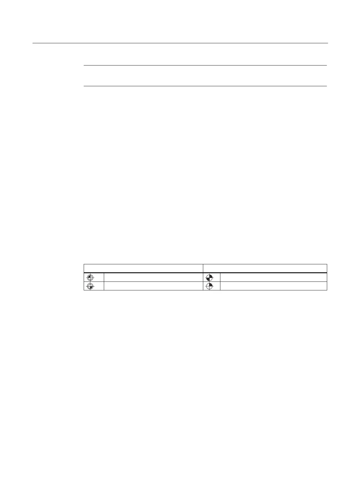
Zero points Reference points
M = Machine zero
R = Reference point
W = Workpiece zero
T = Toolholder reference point
Machine zero M
The machine zero M defines the machine coordinate system MCS. All other reference points
refer to the machine zero.
Workpiece zero W
The workpiece zero W defines the workpiece coordinate system in relation to the machine
zero M. The programmed part-program blocks are executed in the workpiece coordinate
system WCS.

 Loading...


