Detailed Description
2.3 Tool cutting edge
Basic logic functions: Tool Offset (W1)
Function Manual, 11/2006, 6FC5397-0BP10-2BA0
47
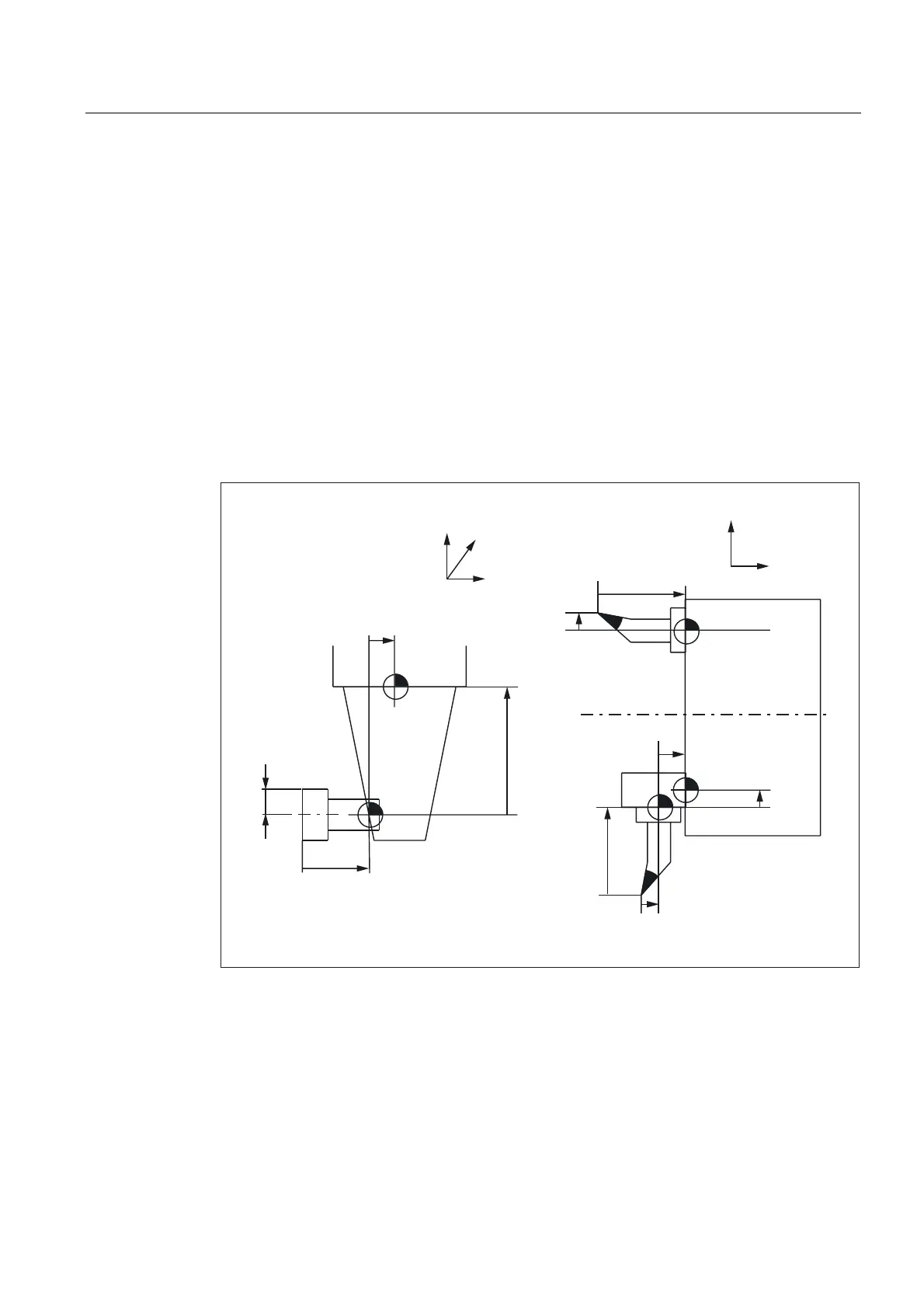
2.3.8 Base-dimension/adapter-dimension tool length compensation (tool parameters 21
to 23)
Meaning
Tool base dimension/adapter dimension can be used when the reference point of the
toolholder (tool size) differs from the reference point of the toolholder.
This is the case when:
• The tool and the tool adapter are measured separately but are installed on the machine in
one unit (the tool size and adapter size are entered separately in a cutting edge).
• The tool is used in a second tool fixture located in another position (e.g., vertical and
horizontal spindle).
• The tool fixtures of a tool turret are located at different positions.
/HQJWK
/HQJWK
7XUQLQJFHQWHU
/HQJWK
/HQJWK
)7RROKROGHUUHIHUHQFHSRLQWV
)7RROKROGHUUHIHUHQFHSRLQWV
7RROEDVH
GLPHQVLRQ
OHQJWK
7RROEDVH
GLPHQVLRQ
OHQJWK
/HQJWK
5DGLXV
0LOOLQJPDFKLQH 7XUQLQJPDFKLQH
7RROEDVH
GLPHQVLRQ
OHQJWK
7RROEDVH
GLPHQVLRQ
OHQJWK
;
=
<
)
=
;
)
)
)
)
Figure 2-11 Example applications for base-dimension/adapter-dimension TLC

 Loading...


