Detailed description
2.7 Program operation mode
Basic logic functions: Mode group, channel, program operation, reset response (K1)
Function Manual, 11/2006, 6FC5397-0BP10-2BA0
105
2.7.6 Channel status
Interface representation
The current channel status is displayed in the interface. The PLC can then trigger certain
responses and interlocks configured by the manufacturer depending on the status at the
interface.
The channel status is displayed in all operating modes.
Channel statuses
The following channel statuses are available at the interface:
• DB21, ... DBX35.7("channel status reset")
• DB21, ... DBX35.6 ("program status interrupted")
• DB21, ... DBX35.5 ("channel status active")
For a further explanation of the individual signals see Chapter 5.
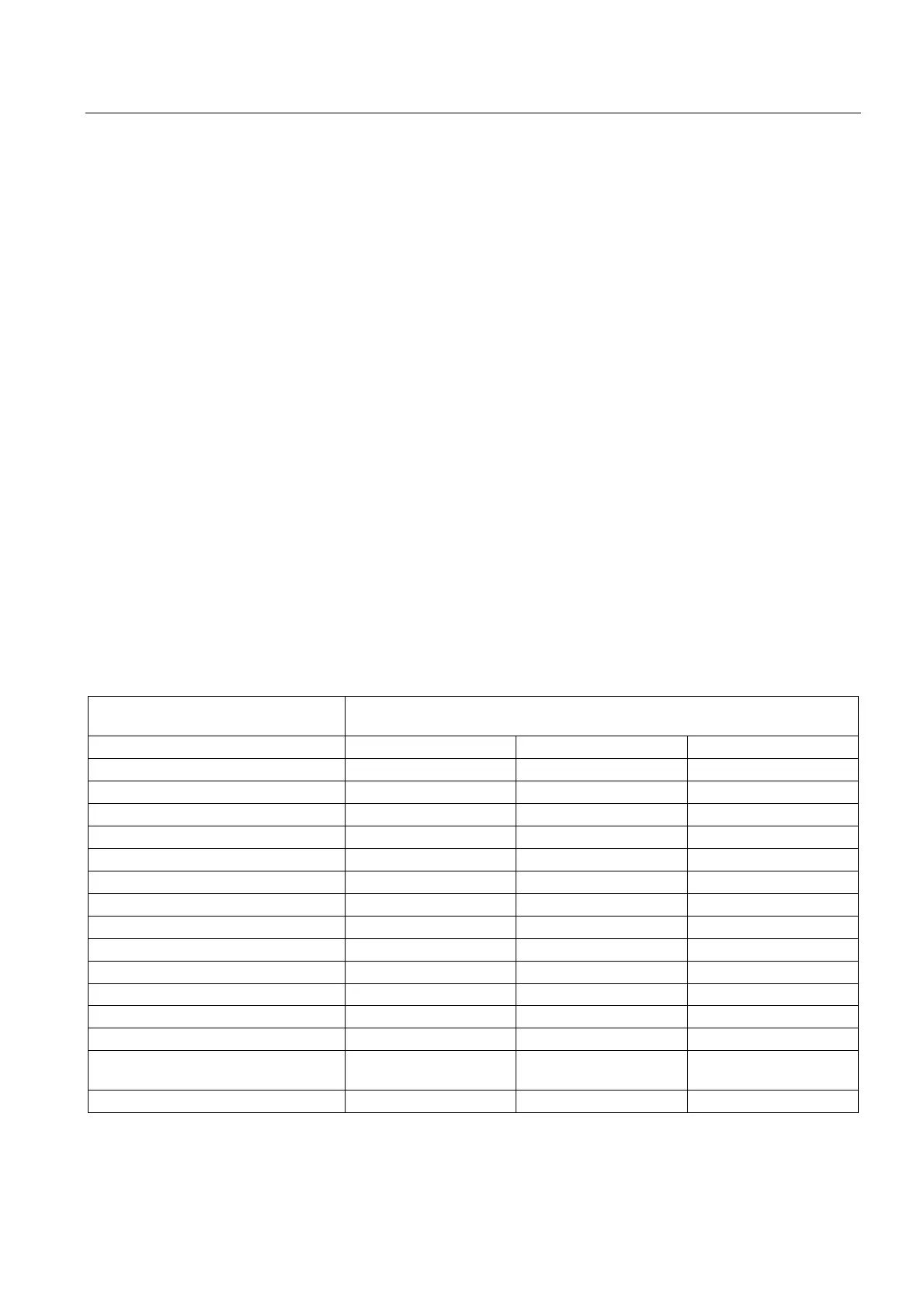
The effect of commands/signals
The channel status can be modified through the activation of various commands or interface
signals. The following table shows the resulting channel status when these signals are set
(assumed status before the signal is set - > Channel status active).
The "Channel status active" signal is obtained when a part program or
part program block is being executed or when the axes are traversed in JOG mode.
Commands
Resulting channel status
Reset Interrupted active
IS "Reset" X
IS "NC Stop" X
IS "NC stop at block limit" X
IS "NC stop axes and spindles" X
IS "Read-in disable" X
IS "Feed stop, channelsp." X
IS "Feed stop, axissp." X
Feed override = 0%
IS "Spindle stop" X
M02/M30 in a block X
M00/M01 in a block X
IS "Single block" X
IS "Delete distancetogo" X
Auxiliary functions output to PLC but
not yet acknowledged
X
Wait instruction in program X

 Loading...


