Detailed Description
2.4 Tool radius compensation 2D (TRC)
Basic logic functions: Tool Offset (W1)
64 Function Manual, 11/2006, 6FC5397-0BP10-2BA0
Example:
An approach is made with G17 starting at position Z=20 of point P
1
. The SAR plane defined
by P
3
is at Z=0. The point defined by DISCL must, therefore, lie between these two points.
MD20204=0.010. If P
2
is between 20.000 and 20.010 or between 0 and -0.010, it is assumed
that the value 20.0 or 0.0 is programmed. The alarm is output if the Z position of P
2
is greater
than 20.010 or less than -0.010.
Depending on the relative position of start point P
0
and end point P
4
with reference to the
machining plane, the infeed movements are performed in the negative (normal for approach)
or positive (normal for retraction) direction, i.e., with G17 it is possible for the Z component of
end point P
4
to be greater than that of start point P
0
.
Programming the end point P
4
(or P
0
for retraction) generally with X.... Y... Z...
Possible ways of programming the end point P
4
for approach
End point P
4
can be programmed in the actual SAR block.
P
4
can be determined by the end point of the next traversing block.
Further blocks (dummy blocks) can be inserted between the SAR block and the next
traversing block without moving the geometry axes.
The end point is deemed to have been programmed in the actual SAR block for approach if
at least one geometry axis is programmed on the machining plane (X or Y with G17). If only
the position of the axis perpendicular to the machining plane (Z with G17) is programmed in
the SAR block, this component is taken from the SAR block, but the position in the plane is
taken from the following block. In this case, an alarm is output if the axis perpendicular to the
machining plane is also programmed in the following block.
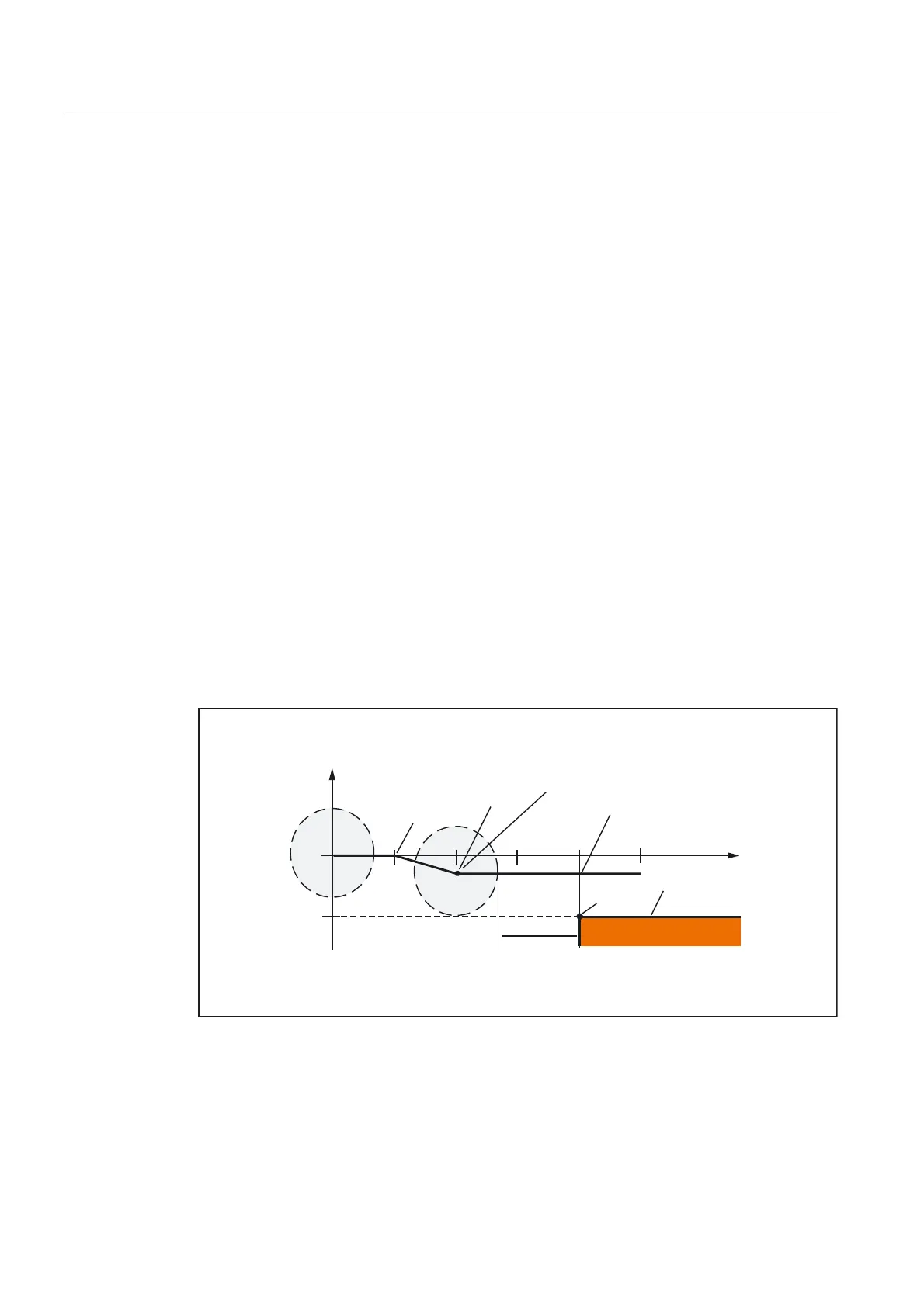
Example:
&RQWRXU
0DFKLQLQJXSWRWKLV
SRLQWZLWK*WKHQZLWK
*)
]
=
=
',65
;
3
<

 Loading...


