Detailed Description
2.8 Special handling of tool compensations
Basic logic functions: Tool Offset (W1)
Function Manual, 11/2006, 6FC5397-0BP10-2BA0
137
Assignment of tools
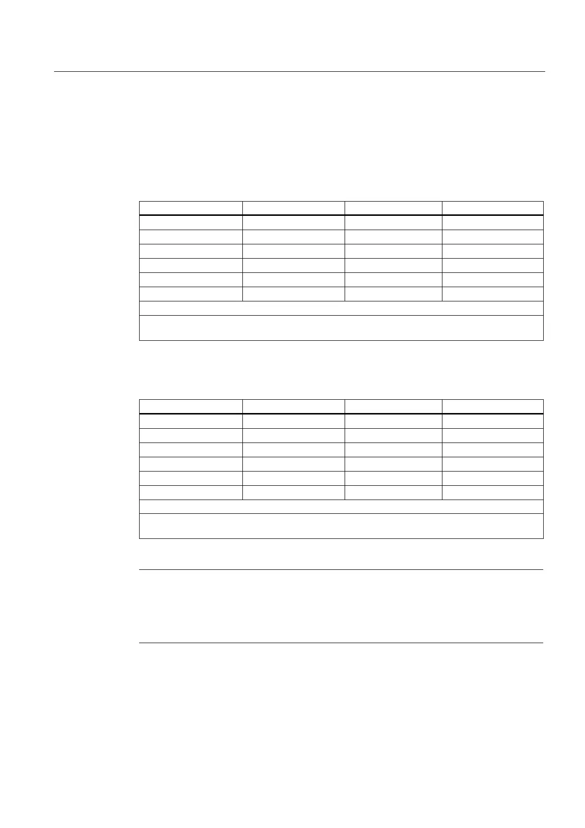
The assignment of tool length components to geometry axes for turning and grinding tools
(tool types 400 to 599) is generated from the value of the following setting data in
accordance with the following table:
SD42940 $SC_TOOL_LENGTH_CONST (change of tool length components on change of
planes).
Layer Length 1 Length 2 Length 3
17 Y X Z
*) X Z Y
19 Z Y X
-17 X Y Z
-18 Z X Y
-19 Y Z X
*) Each value not equal to 0, which is not equal to one of the six listed values, is evaluated as value
18.
The following table shows the assignment of tool length components to geometry axes for all
other tools (tool types < 400 or > 599):
Layer Length 1 Length 2 Length 3
*) Z Y X
18 Y X Z
19 X Z Y
-17 Z X Y
-18 Y Z X
-19 X Y Z
*) Each value not equal to 0, which is not equal to one of the six listed values, is evaluated as value
17.
Note
For representation in tables, it is assumed that geometry axes 1 to 3 are named X, Y, Z. The
axis order and not the axis identifier determines the assignment between a compensation
and an axis.
Three tool length components can be arranged on the 6 different types above.

 Loading...


