Detailed Description
2.16 Feeds (V1)
Basic logic functions: NC/PLC interface signals (Z1)
Function Manual, 11/2006, 6FC5397-0BP10-2BA0
131
DB21, ...
DBB4
Feed rate override
Signal state 1 or
edge change
0 → 1
The feed rate override can be defined via the PLC in binary or Gray coding.
With binary coding, the feed value is interpreted in %.
0% to 200% feed changes are possible, in accordance with the binary value in the byte.
The following permanent assignment applies:
&RGH
)HHGUDWHRYHUULGHIDFWRU
ฬ
ฬ
ฬ
ฬ
ฬ
Binary values > 200 are limited to 200%.
The machine data:
MD12100 $MN_OVR_FACTOR_LIMIT_BIN (limit for binary-coded override switch)
can be used to additionally limit the maximum feed rate override.
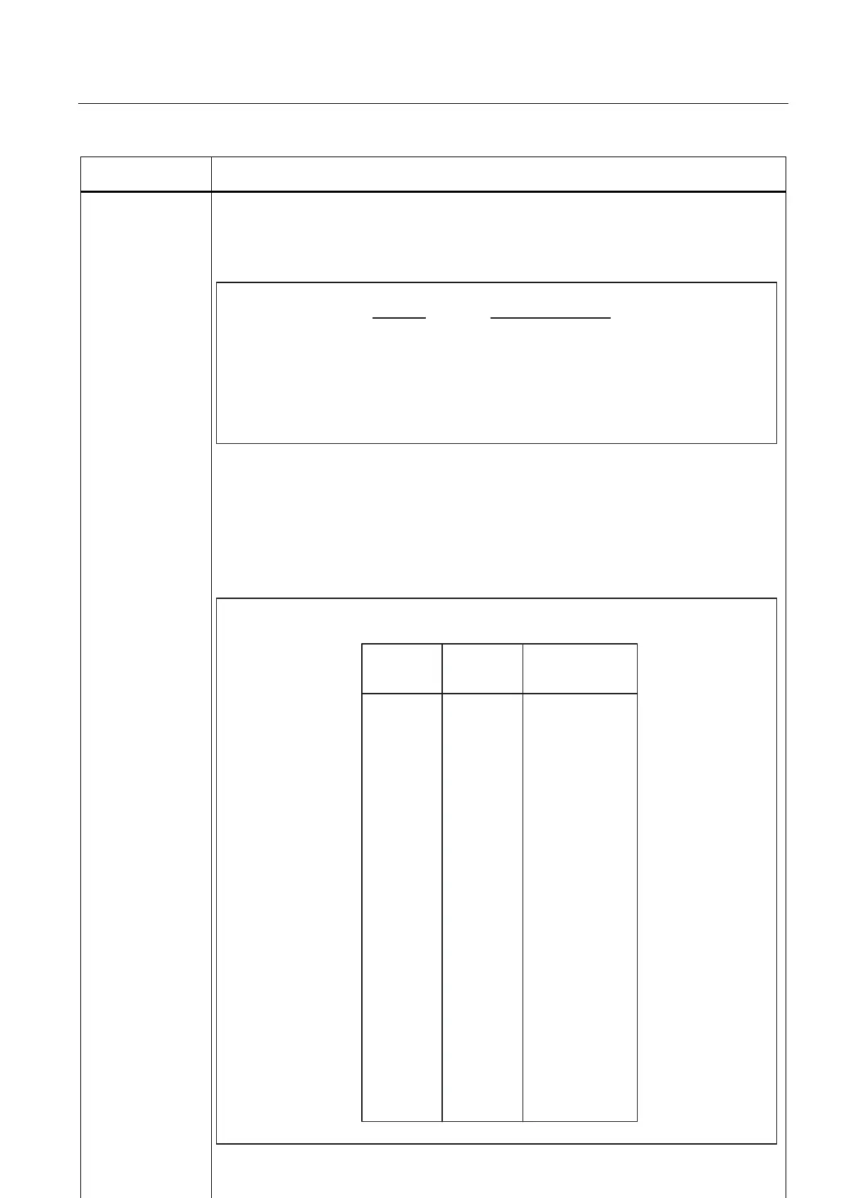
With Gray coding, the individual switch settings are assigned to the following codes:
7DEOH*UD\FRGLQJIRUIHHGUDWHRYHUULGH
6ZLWFK
SRVLWLRQ
&RGH )HHGUDWH
RYHUULGHIDFWRU
VWDQGDUGYDOXHV

 Loading...


