Detailed description
2.3 Coordinate systems
Basic logic functions: Axes, coordinate systems, frames (K2)
Function Manual, 11/2006, 6FC5397-0BP10-2BA0
43
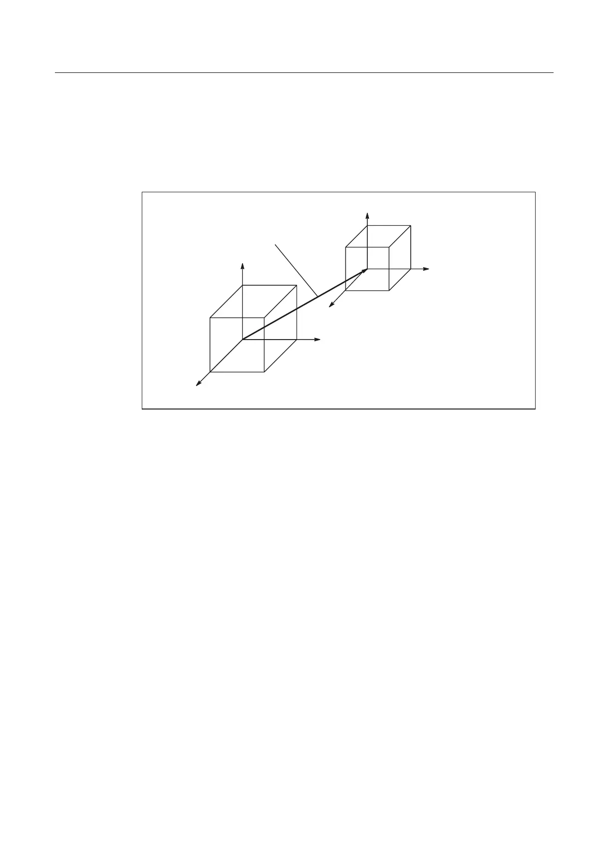
Machine tools with kinematic transformation
The BCS and MCS do not coincide when the BCS is mapped onto the MCS with kinematic
transformation (e.g., TRANSMIT / face transformation, 5-axis transformation or more than
three axes).
On such machines the machine axes and geometry axes must have different names.
<
;
=
;
=
<
0&6
%DVLFFRRUGLQDWHV\VWHP%&6
0DFKLQHFRRUGLQDWHV\VWHP0&6
.LQHPDWLFBWUDQV
IRUPDWLRQ
%&6
%&6
%&6
0&6
0&6
Figure 2-16 Kinematic transformation between the MCS and BCS
Machine kinematics
The workpiece is always programmed in a two or threedimensional, rightangled coordinate
system (WCS). However, such workpieces are being programmed ever more frequently on
machine tools with rotary axes or linear axes not perpendicular to one another. Kinematic
transformation is used to represent coordinates programmed in the workpiece coordinate
system (rectangular) in real machine movements.
References:
/FB3/Function Manual, Special Functions; 3-Axis to 5-Axis Transformation (F2)
/FB2/Function Manual, Extension Functions; Kinematic Transformation (M1)

 Loading...


