Connecting
9.3 Connecting the compact starter without optional AS-i mounting module
SIRIUS 3RA6 Compact Starter
76 System Manual, 02/2008, GWA 4NEB 560 0601-02 DS 02
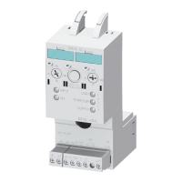
Table 9-4 Pin assignments for 3RA62 compact starter reversing starter
Terminal Description Image
1L1, 3L2, 5L3 Main conductor terminals (line side)
A1+, A2/B2-, B1+ Control voltage connection
(AC/DC 24 V, 42 - 70 V or 110 - 240 V)
A: Direction of rotation 1
B: Direction of rotation 2
95, 96, 98 "Overload" signaling switch (CO contact)
77, 78 "Fault" signaling switch, e.g. "Short circuit"
→ actuator set to
OFF/TRIPPED (NO
contact)
13, 14 Auxiliary NO contact
for querying the position of the main
contacts
(direction of rotation 1)
43, 44 Auxiliary NO contact
for querying the position of the main
contacts
(direction of rotation 2)
2T1, 4T2, 6T3 Main conductor terminals (outgoing side)
$
$%
12
&
1&
12 12 12
7 7 7
%
WARNING
/ / /
Note
If a mirror contact is required in conjunction with a reversing starter, the external auxiliary
switch block (optional) must be used for this purpose.

 Loading...