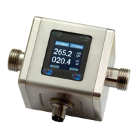
1010GCNFM-3C
Index
Index-1
Index
Symbols
1011 Series Transducers 5-1
CC129 Thickness 4-12
FUG1010GCN Clamp-on Gas Flowmeter 2-1
A
Absolute Flow 4-42
Vf, Vfo, Vfo2, Vs, Vsg 4-42
Accuracy 6-1
Active Memory 4-1, 6-4
Actual Zero 4-28
AGA8 Comp 4-15
Installation Instructions 4-16
Table Generation 4-16
Alarm Letter Codes And Descriptions 4-52
Alarm Levels, setting 4-44
High Base S.G. 4-45
High Flow 4-44
High S.G. 4-45
High Temperature 4-45
High Viscosity 4-45
Interface SG, Interface Vs (m/s) 4-45
Low Base S.G. 4-45
Low Flow 4-44
Low S.G. 4-45
Low Temperature 4-45
Low Viscosity 4-45
Makeup Latch 4-46
Turbulence % 4-45
Alphanumeric Strings 3-4, 3-6
Analog Input Setup 4-59
Setting Current Input 4-60
Analog Out Setup 4-57
Outputs 4-57
Setup Data Categories 4-57
Table to determine proper I/O Installation Drawings 4-57
Assigning Functions
Io 4-57
Vo 4-58
Pgen, Vo 4-58
Analog Output Trim 6-11
Analog Output Trim Menu 4-84
Analog Output Span 4-57
AnCal 4-63
Application Info Menu 4-64
Menu Items 4-64
Application Notes, System 1010 6-1
Axial Alignment 5-6

 Loading...


