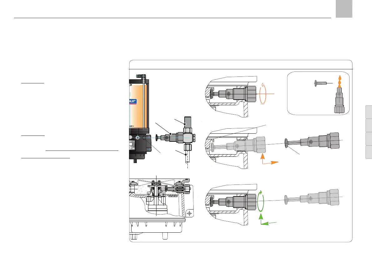
Assembly, positively driven pump element, Fig. 9
1
2
3
1
2
3
Section A
Section B
Section D
Section C
the housing bore with a bar magnet (or
taper-nose pliers).
• Section C Carefully pull the piston (6) out of
the new pump element (1)
• Coat the bore of the pump element lightly
with grease
• Insert the piston in the bore of the pump
element, leaving as much of the piston as
possible protruding from the bore
• Section D Slowly insert the pump element (1)
at an angle into the housing bore (5) until
the piston bottoms out under the guide of
the eccentric ring (4)
• Straighten the pump element (1) horizon-
tally and screw it into the housing bore (5)
by hand
• Tighten pump element (1) at a torque
of 35 Nm.
• Switch on pump and leave running until
grease without bubbles discharges from the
pump element outlet.
•
Connect pressure regulating valve (2) (or
lubrication line (3) to the pump element (1 )
and tighten at a torque of 25 Nm
6
4
5
Insert pump element (1) into
housing hole (5) and twist in
by hand!
KFG KFGS KFGL KFGCKFG KFGS KFGL KFGC
Page 25
EN
Assembly instructions