3V2V1
1
1
1
1
1
1
2
2
2
2
2
2
3
3
3
3
3
3
4
4
4
4
4
4
1
2
3
4
1
2
2
1
2
1
2
1
1
2
3
4
1
2
3
4
1
2
3
4
A B C
1 2
3
4
5 6
7
X1
BN
RD-BK
BU
PK
BK
BK
VT-GN
CAN-BUS
M12x1
1x21M1x21M
M12x1
1x21M1x21M
M12x1
1x21M1x21M
M12x1
F1
S1
M L
31 30
15
CS4 (MC)
V4
SL2
RD
CS1
CS1
CS2
CS2
CS3
CS3
V1 V2 V3
+++++++ + +
–– – – –
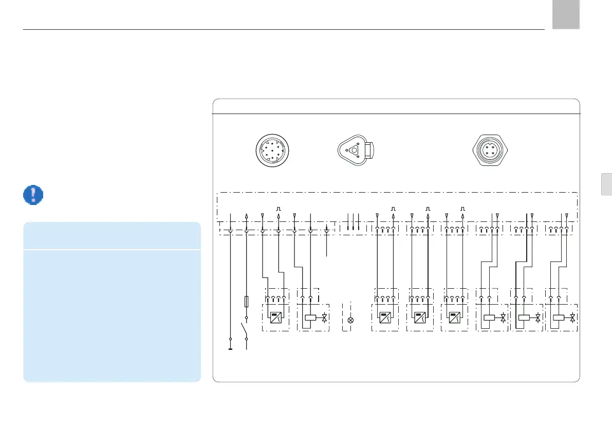
4.9.2 Connectivity
Example of the connection of four reversing
valves and four piston detectors for units with
maximum configuration (6x circular connectors
M12x1 available) for the operation of a pro-
gressive feeder system, divided into four lubri-
cation segments
A
B
C
CS.. = piston detector V.. = reversing valves
2
4
5
3
1
6
7
34
1 2
Assignment of the 7-pin
circular connector
Assignment of the 4-pin circular
connector M12x1
possible.
Legend for maximum configuration connection
example
CS1 – CS4 Piston detector 1 – 4
V1 - V4 Valves 1-4
MC Machine contact
SL2 "Fault" indicator light
(can be operated as an
alternative in place of valve 4)
L+ + Supply voltage potential
S1 Ignition switch
F1 Fuse
Assignment of the
CAN bus connector
KFGC
Maximum configuration example, Fig. 28
Page 39
EN
Assembly instructions