4.3.4 Pump elements with positively driven pistons
1) The values given here apply for a temperature of 20 °C, back pressure of 50 bar and greases of NLGI Grade 2.
Labeling,
see table, labeling column
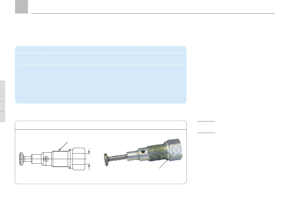
Positively driven pump elements G-1 without pressure regulating valve, Fig. 8
M14x1,5
see Fig. 9
• Turn off pump unit.
• Unscrew and remove screw plug
(KFG1.128)
Then perform the following:
• Loosen and remove pressure regulating
valve (2) (or lubrication line (3) on an
already mounted pump element (1).
• Switch off the pump unit as soon as the
pump element to be changed (1) begins
pumping. (To position the eccentric ring).
• Section A Disengage the installed pump
element (1) and slowly unscrew it out
• Section B
thread, slightly raise the pump element (1)
so that the piston comes out of the eccen-
tric ring (4)
• Carefully pull the pump element (1) out
of the housing bore (5), making sure that
the piston (6) is not pulled out of the pump
element
If the piston does come loose while pulling
out the pump element, remove it from
KFG KFGS KFGL KFGCKFG KFGS KFGL KFGC
Pump elements with positively driven pistons
Delivery rate
1
) Max. permiss. oper. pressure Labeling Order No.
[cm
3
/min] [bar]
5.0 250 L-0 KFG1.U0-E
2.5 350 G-1 KFG1.U1-E
1.8 350 H-2 KFG1.U2-E
1.3 350 J-3 KFG1.U3-E
4.3.3 Assembly of a pump element with
positively driven pistons
Optional pump element outlet G 1/4 “
Page 24
EN
Assembly instructions