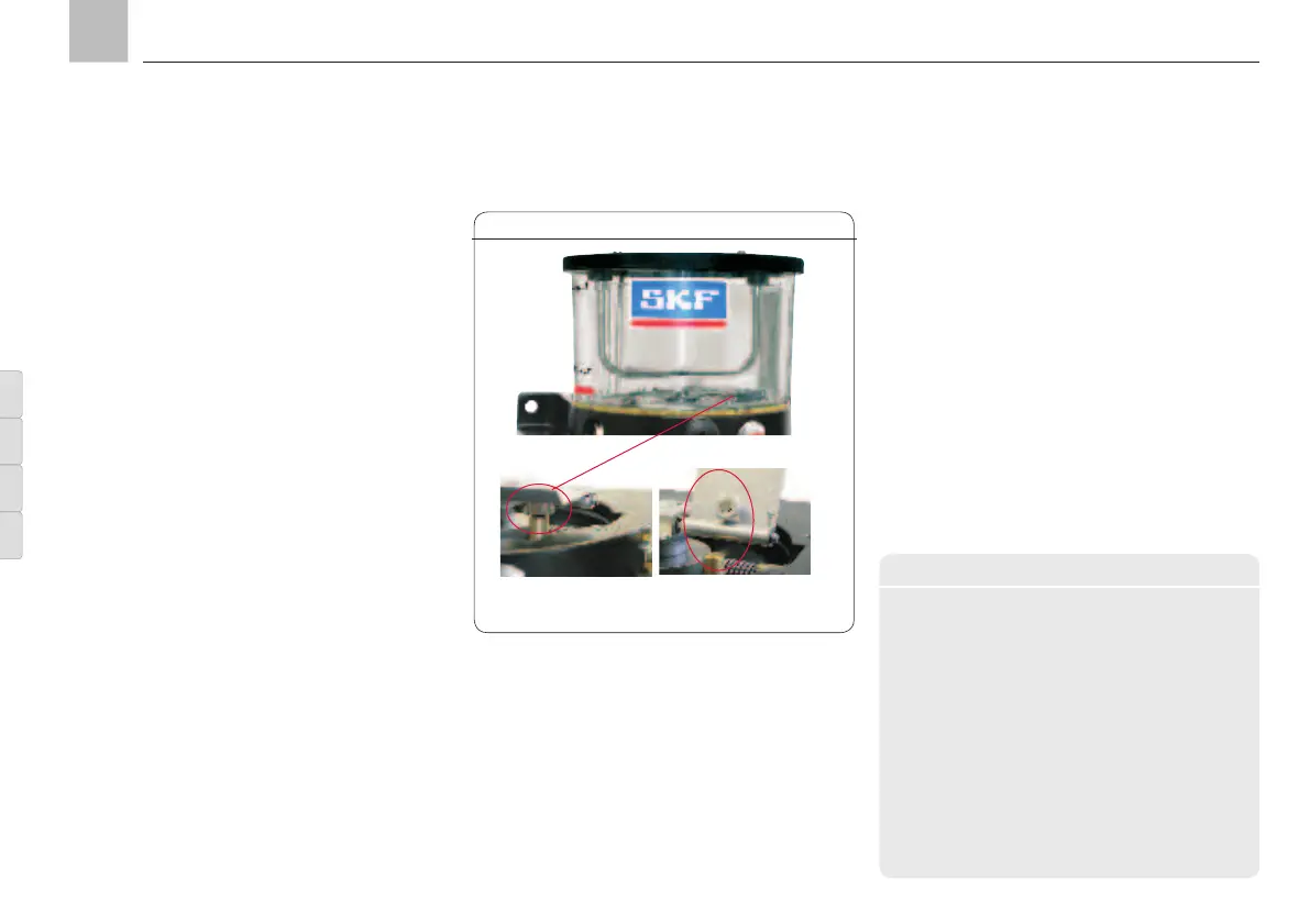
Fill level monitoring W1, Fig. 30
4.11 Fill level monitoring
Two different fill level switches can be fitted as
standard on the KFGS and KFGL pump units for
the purpose of indicating the “Minimum” lubri
-
cant fill level
Order code 1 (formerly W1 control) for
greases of NLGI ≥ 2
Order code 2 (formerly W1G control) with
signal smoothing, for greases of NLGI ≥ 2
With pump design KFG (without control unit)
with fill level monitoring the monitoring signals
are processed by a system provided by the
customer;
in the KFGS and KFGL versions the monitoring
switch is connected to the pump's control sys-
tem. This effectively prevents the fill level from
falling below the minimum, thus preventing any
damage to the KFG pump units which could
result from that.
On KFGC pump units, fill level control is cus-
tomized according to customer specifications.
4.11.1 Order code 1 (W1)
max. 24 VDC, for greases of NLGI Grade ≥ 2
Technical data
Fill level monitoring
Function ............. Mechanical, by dry
reed contact
Contact form .......... NO-contact
Switching capacity, max. .. 0.6 W
Switching voltage, max.... 24 VDC
Switched current, max. ... 25 mA;
resistive load only
1
)
Plug-in connection DIN EN 60947/IEC 947
2
)
Wiring diagram Circular connector M12x1
1) No inductive load, no lamp load (indicator lamp)
2) Cable socket - see Accessories Chapter 16
Functional description
The fill level switch W1 is designed as a rocker
switch integrated in the base of the reservoir. A
magnetic rocker mounted on the agitator is
pushed down by resistance from the grease
when the reservoir is full. A pulse is generated
with every revolution of the agitator. When the
minimum fill level is reached, the resistance
from the grease on the rocker gives way. The
rocker then snaps back up and the pulse is
interrupted.
KFG KFGS KFGL KFGC
Contact W1 open,
fault position
Contact W1 closed,
go position
Page 42
EN
Assembly instructions