4.7.1 KFGS power supply4.7 KFGS power supply and connections
With integrated IG502 control unit
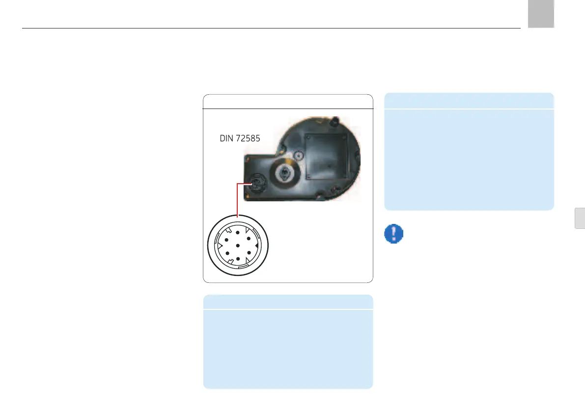
The electrical connection is a 7-pin plug-in
connector on the base of the pump unit.
The pump control can run in the following
control modes:
Timer operation without system monitoring
Timer operation with system monitoring
Counter operation without system
monitoring
Counter operation with system monitoring
Depending on the pump unit design, an addi-
tional plug for fill level control can be integrat-
ed into the pump housing. The standard con-
nections are presented below.
2
4
5
3
1
6
7
Connector pin assignment
PIN Color code Conductor coloring
1 BN Brown
2 RD-BK Red-Black
3 BU Blue
4 PK Pink
5 BK Black
6 BK Black
7 VT-GN Violet-green
Note!
The connector pin assignment varies
depending on the operating mode.
Therefore refer to the following ex-
amples for pin functions. Unneeded
conductor ends on the cable set must
be individually insulated and secured so
that no short to ground can occur.
Power supplied through a
7-pin circular connector
Accessories
Description Order No.
Wiring harness, in corrugated pipe,
with socket-outlet on pump side
8 m length 997-000-760
12 m length 997-000-630
16 m length 997-000-650
KFGS
KFGS power supply, Fig. 17
Page 31
EN
Assembly instructions