Assembly instructions
4.7.4 Connectivity
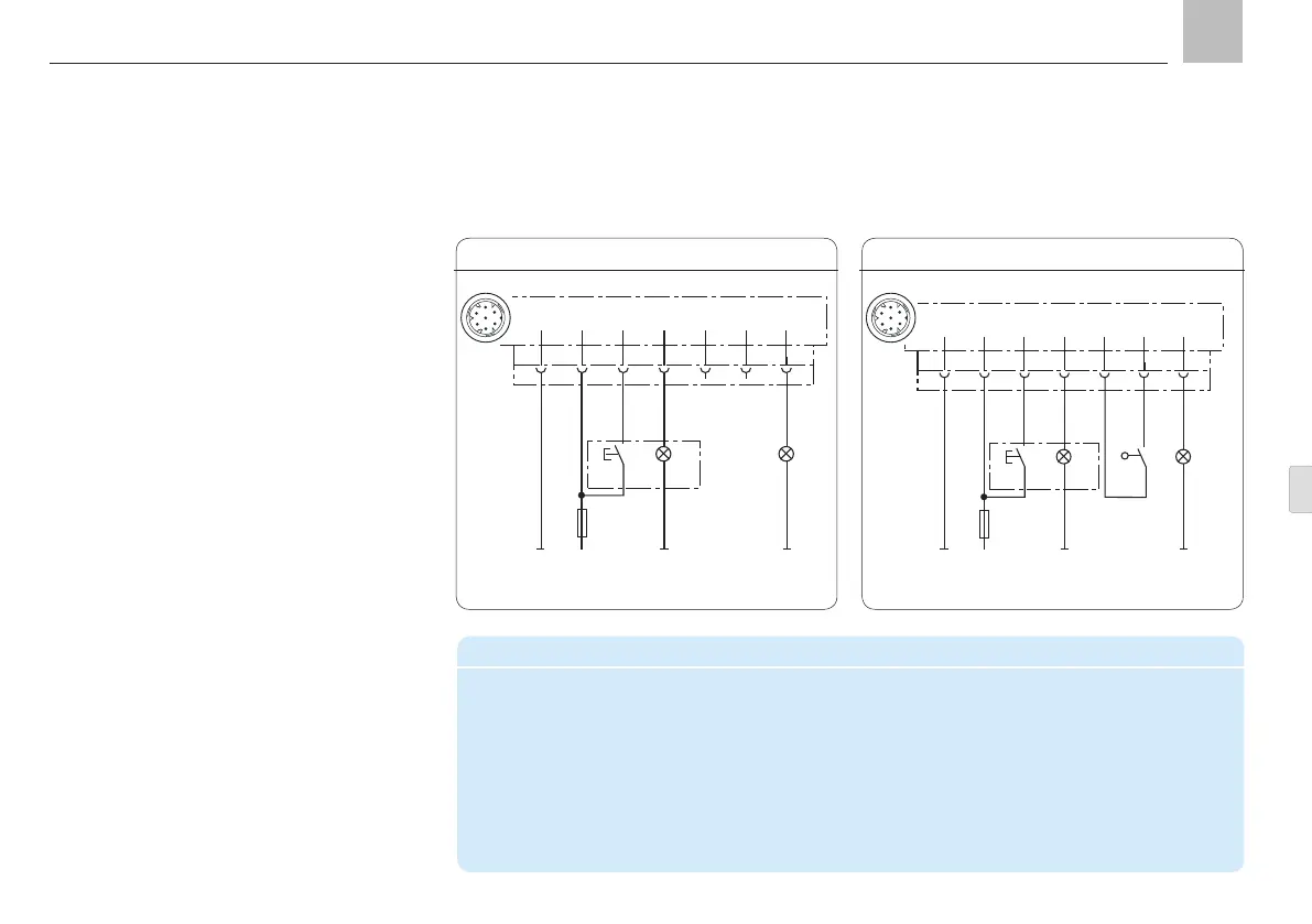
Timer operation without system monitoring
Connector pin assignment in timer operation
PIN Code Assignment
1 31 - Supply voltage potential (0 V, GND)
2 15 + Supply voltage potential "ignition ON"
4 SL2 "Fault" indicator light
5 ZS Piston detector „+“
6 ZS Piston detector "Signal"
7 SL1 "Pump ON" indicator light
4.7.5 Connectivity
Timer operation with system monitoring
Programming: tPA, tCO, COP = OFF
1
BN
KFGS...
F
2 3 4 5 6 7
X1
RD-BK
BU
PK
VT-GN
DK
SL2
2,4 W
31 15
SL1
2,4 W
1
BN
KFGS...
F
2 3 4 5 6 7
X1
RD-BK
BU
PK
VT-GN
DK
SL2
2,4 W
SL1
2,4 W
BK
BK
PS
+
31 15
Timer mode
In timer mode, the interval time is determined
by a time value. It is configured by entering a
time value in hours.
The pump cycle time is configured using a
time value in minutes.
The fill level monitoring unit (W1 control) is in-
ternally connected to the integrated pump
control unit. A fault notification can be sent to
the vehicle control/electronics system via indi-
cator light SL2.
2
4
5
3
1
6
7
Programming: tPA, tCO, COP = CS
Programming:
- see Chapter 9 of with assembly instructions
2
4
5
3
1
6
7
KFGS
KFGS connection, Fig. 20 KFGS connection, Fig. 21
Page 33
EN