31 15
1
BN
KFGS...
F
2 3 4 5 6 7
X1
RD-BK
BU
PK
DK
SL2
2,4 W
Programming:
- Chapter 9 of assembly instructions
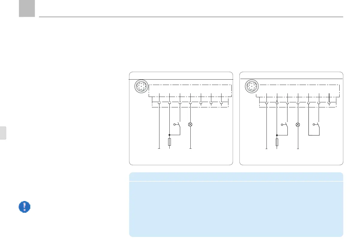
4.7.2 Connectivity
Counter operation without system monitoring
Connector pin assignment in counter operation
PIN Code Assignment
1 31 - Supply voltage potential (0V, GND)
2 15 + Supply voltage potential ("ignition ON")
4 SL2 "Fault" indicator light
5 ZS Piston detector „+“
6 ZS Piston detector "Signal"
7 SL1 "Pump ON" indicator light
4.7.3 Connectivity
Counter operation with system monitoring
31 15
1
BN
KFGS...
F
2 3 4 5 6 7
X1
RD-BK
BU
PK
DK
SL2
2,4 W
BK
BK
ZS
Programming: cPA, tCO, COP = CS
One pulse is counted each time the
operating voltage is switched on when
the pushbutton is closed in counter
operation.
Control using machine pulses
(Counter mode = load-dependent lubrication)
The duration of the interval time is determined
by a pulse generator that sends pulses to the
control unit based on how long the machine
has been running. The control unit counts the
pulses that are received and starts the pump
after the pre-set number of pulses.
The pump cycle time is defined by a time val-
ue. Both the number of pulses that determine
the interval time and the pump cycle time can
be configured.
The fill level monitoring unit is internally con-
nected to the integrated pump control unit. A
fault notification can be sent to the process
control level via indicator light SL2.
Assembly instructions
Programming: cPA, tCO, COP = OFF
2
4
5
3
1
6
7
2
4
5
3
1
6
7
KFGS
KFGS connection, Fig. 18
KFGS connection, Fig. 19
Page 32
EN