1
2
3
4
1
2
B C
1 2 3 4 567
X1
BN
RD-BK
BU
PK
BK
BK
VT-GN
CAN-BUS
M12x1
F1
S1
M L+
31 30
15
CS4 (MC)
V4
SL2
RD
KFGS...-...B...
+ + +
––
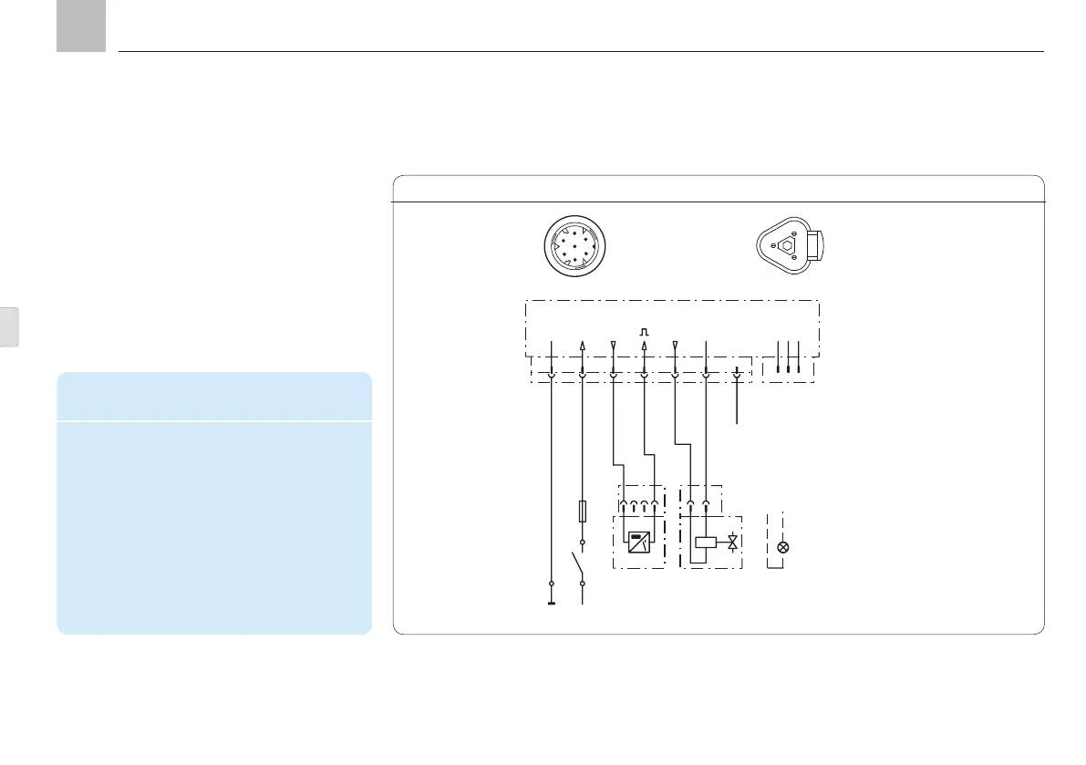
Example of the connection of a piston detector
or machine contact and a reversing valve on a
unit with minimum configuration (without
circular connector M12x1) for operation of a
progressive feeder system, no division into
lubrication segments.
Piston detector
Assignment of the 7-pin circular connector
2
4
5
3
1
6
7
A
B
C
Legend for minimum configuration
connection example
CS4 Piston detector 4
V4 Valves 4
MC Machine contact
SL2 "Fault" indicator light
(can be operated as an alternative in
place of valve 4)
L+ + Supply voltage potential
S1 Switch
F1 Fuse
Assignment of the CAN bus connector
V.. = reversing valves
KFGC
Minimum configuration example, Fig. 29
Page 40
EN
Assembly instructions