block diagram W1
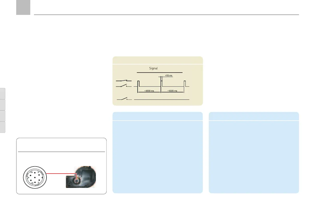
Function
Reservoir full
Reservoir empty
Connector pin assignment W1 (pump unit)
PIN Description
1 = 31 - Supply voltage potential
(0V, GND)
2 = 15 + Supply voltage potential
3 = Not assigned
4 = Not assigned
5 = + Potential
6 = Signal (pulses)
7 = Not assigned
monitoring, order code 1 and 2
The standard model of the KFG pump unit is
not fitted with fill level monitoring.
KFG models with fill level monitoring need to
be connected to an external system (provided
by the customer) because there is no control
system to process the signals. In this optional
version, the cubical plug fitted on the side is
replaced by a 7-pin connector fitted on the
bottom of the KFGS and KFGL. The following
lists the pin assignment for the fill level switch-
es with order codes 1 (W1) and 2 (W1G).
Type: W1G
Connector pin assignment W1G (pump unit)
PIN Description
1 = 31- Supply voltage potential
(0V, GND)
2 = 15 + Supply voltage potential
3 = NC (pin 5 and pin 3 closed,
reservoir empty)
4 = NO (pin 5 and pin 3 closed,
reservoir full)
5 = COM (+ potential)
6/7 = Not assigned
Type: W1
Connection, fill level monitoring, W1/W1G,
Fig. 30
KFG KFGS KFGL KFGC
Page 44
EN
Assembly instructions