6. Functional description in progressive systems
KFG
6. Functional description in progressive systems
A general progressive feeder system consists
of the following components:
• Pump unit with pump element and
pressure regulating valve
• Lubrication lines, consisting of main and
possibly branch lines, as well as
• Progressive feeders.
When the pump motor is turned on, the pis-
ton pump delivers lubricant from the lubricant
reservoir to the lubricant outlet. The pump el-
ement attached to the outlet delivers the lubri-
cant further, into the downstream main line.
The lubricant flows through the main line to
the progressive feeder. There, the lubricant is
distributed according to the volume required by
the lubrication point being supplied.
In progressive systems with a master feeder
and secondary feeder, the lubricant coming
from the pump unit is delivered to the master
feeder. The master feeder distributes the lubri-
cant to the secondary feeders according to their
individual volume requirements. From there,
the lubricant flows to the lubrication points.
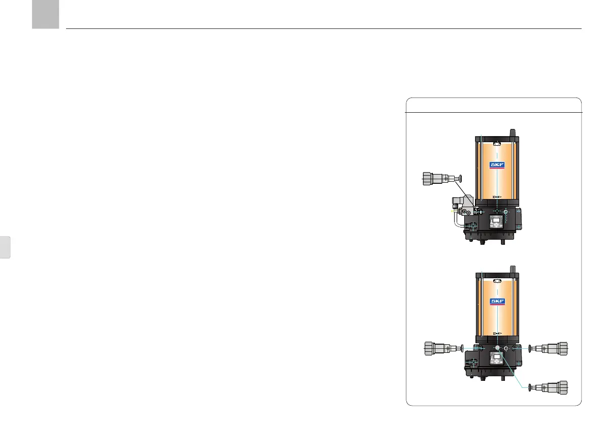
6.1.1 Pump element
The pump element or elements meter out the
lubricant and convey it to the downstream lu-
brication points or distributors. Five different
pump elements are available for the range
from 0.8 to 5 cm
3
/min, according to the lubri-
cant volume required (
see sections 4.3.2 and
4.3.4 in the assembly instructions).
6.1 Functional description for progressive
systems with a KFG pump unit
1
2
3
2
3
1
1
2
3
max
max
Layout of the pump elements, Fig. 1
Page 56
EN