7.3 Functional description in single-line
systems with a KFGC (CAN-Bus)
pump unit
The general functional description for sin-
gle-line systems with a KFG pump unit also
applies for the design with CAN bus pump
control.
7.3.2 Multiple lubrication zones
Using the integrated LC-CAN 5000 control
unit, a single-line system can be divided into
up to four individually controllable lubrication
zones. This is performed using electric switch
valves which separate the individual lubrication
zones from each other.
Four configurable digital inputs/outputs are
available to control each lubrication zone. This,
as well as the type of valves used, provides
various possibilities for setting up lubrication
zones.
7.3.1 Systems with 3/2 directional
solenoid valves
Directional solenoid valves can be used to cre-
ate a single-line system with up to four lubri-
cation zones. The system can be equipped with
or without functionality to monitor pressure
build-up and reduction.
7. Functional description in single-line systems
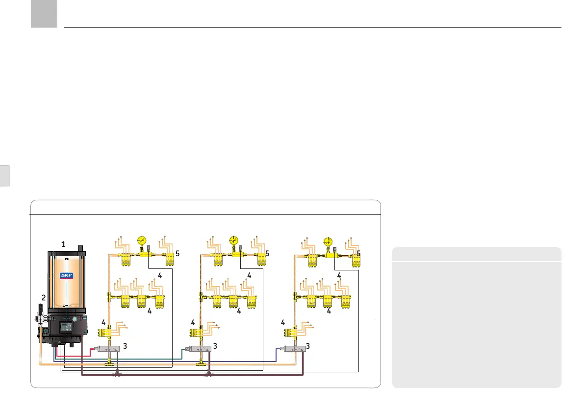
Example of single-line system with KFGC pump unit, Fig. 9
max
Lubrication zone 1 Lubrication zone 2 Lubrication zone 3
KFGC
Legend
monitoring
2 Pressure regulating valve
Lubrication zone 1/2/3
3 Valve for pressure build-up and relief
4 Single-line distributor
5 Pressure switch for pressure build-up monitoring
Page 64
EN