108
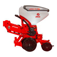
Fig. 7.1
1
2
Fig. 7.2
3
4
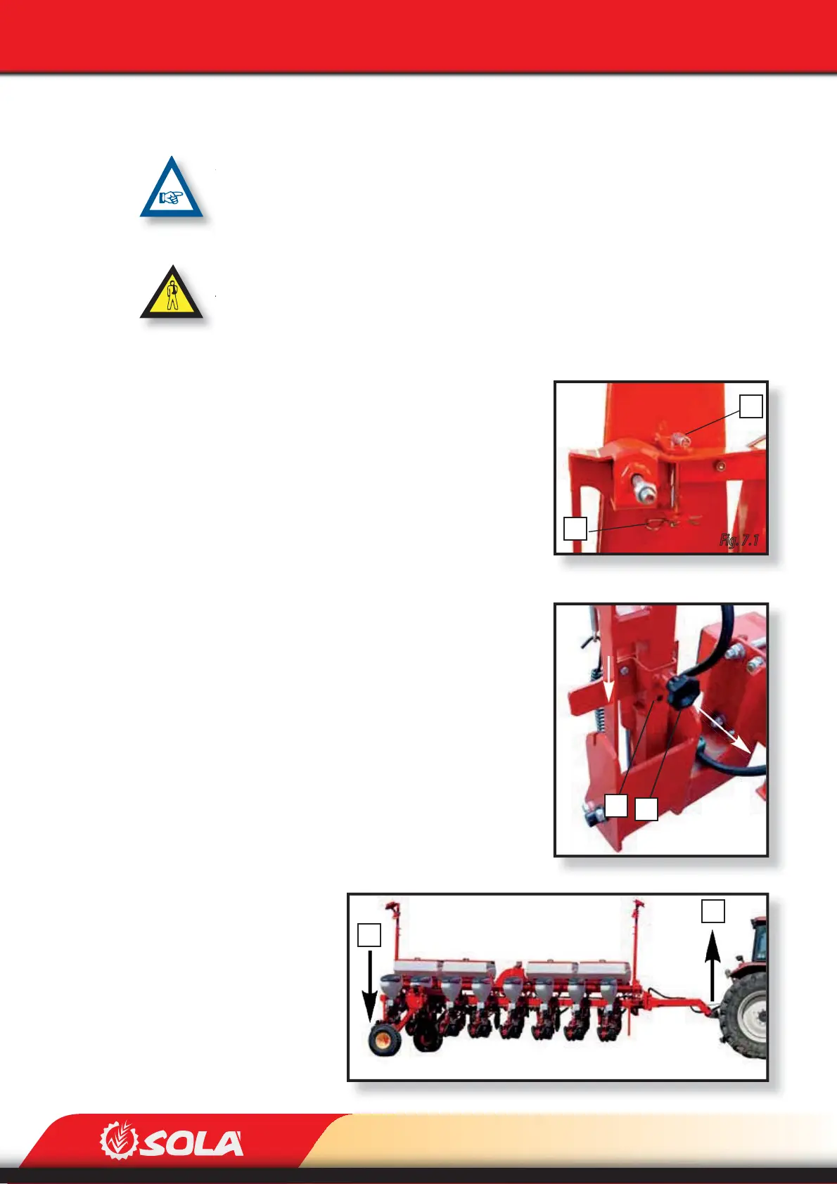
Fig. 7.3
1º
2º
TRANSPORT
7- TRANSPORT
ALL MACHINES CAN RUN ON PUBLIC ROADS, YET ARE PROHIBITED IF EQUIPPED WITH FIXED
FRAME OR VARIANT MANUAL FIXED FRAME WHOSE WIDTH IS NOT ALLOWED ACCORDING TO
EACH COUNTRY’S LEGISLATION. IN THESE CASES, RUNNING ON PUBLIC ROADS WILL ONLY BE
LEGAL IF THE MACHINE HAS THE OPTIONAL LONGITUDINAL TRANSPORT TROLLEY.
BEFORE FOLDING OR UNFOLDING THE TRACK MARKERS, MAKE SURE NO HIGH-VOLTAGE OVER-
HEAD LINES HANGING TOO LOW, SINCE THE TRACK MARKERS MAY TOUCH THEM AS RESULT OF
THE ADJUSTMENTS PERFORMED TO THEM OR DUE TO THE TERRAIN’S CONDITIONS.
7.1 FIXED FRAME
To set planters with ALLOWED FRAME WIDTH for transit:
1- Fold the track markers. Once they are folded, their position needs
to be locked by following next steps. Depending on the type of
track marker (A or B) do as required:
A. Place the security handle (2, Fig. 7.1) and, next, place the
pin (1, Fig. 7.1).
B. Pull the knob (3, Fig. 7.2) and shift the xing piece down-
wards until it ts into the transit position (4, Fig. 7.2).
2- Raise the planter.
To set planters with LONGITUDINAL TRANSPORT TROLLEY for transit:
1- Fold the track markers. Once they are folded, their position needs
to be locked by following next steps. Depending on the type of
track marker (A or B) do as required:
A. Remove the pin (1, Fig. 7.1) and remove the securing
handle (2, Fig. 7.1).
B. Pull the knob (3, Fig. 7.2) and shift the xing piece up-
wards until it ts into the working position (4, Fig. 7.2).
2- Uncouple the planter from the tractor and disconnect all electric
and hydraulic connections.
3- Unfold the drawbar so that it stays aligned to the planter’s frame.
4- Couple the planter’s drawbar to the tractor using the tractor’s two
low points. Plug the drawbar’s
hydraulic connection to the
tractor.
5- Lower the transport wheels
(1, Fig. 7.3) until the side of the
planter where the transport
wheels are attached raises.
6- Raise the tractor’s two lower
arms (2, Fig. 7.3).