79
A
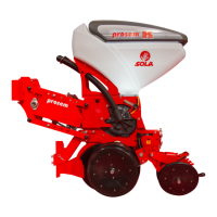
Fig. 6.91
1
C
B
1
2
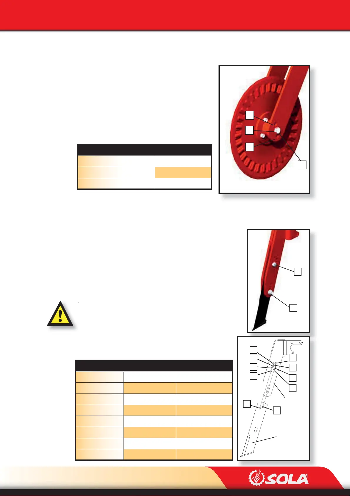
Fig. 6.92
ADJUSTMENTS
6.12.2
ADJUSTING THE DISC FURROW OPENER IN UNIT PROSEM K
(OPTIONAL)
To adjust the disc opener’s working depth:
1- Remove the nut (1, Fig. 6.91), hold the disc with one
hand and use the other one to remove the screw.
2- Place the disc at the desired position, A, B or C.
3- Place the screw at the same position as the disc and
x it using the nut.
6.12.3 ADJUSTING THE FURROW-OPENER BLADE (OPCIONAL)
To adjust the blade’s working depth:
1- Remove both the nut and the position screw (1, Fig. 6.92)
2- Loosen both the nut and the xing screw (2, Fig. 6.92)
3- Place the blade at the desired height, adjust the height
until one of the holes (A or B, Fig. 6.93) ts another one.
The xing screw (1, Fig. 6.93) needs to be placed at the same letter
in both the blade and the support. Positions A and B ARE NOT
INTERCHANGEABLES. To adjust the blade’s working depth de-
pending on the position of the position screw (1, Fig. 6.92), see next
table and picture 6.93:
DISC OPENER’S POSITION DEPTH (cm)
A 0
B 2
C 4
BLADE’S POSITION SUPPORT’S POSITION DEPTH CM)
A A1 0
B B1 0,7
A A2 1,4
B B2 2,2
A A3 2,9
B B3 3,6
A A4 4,3
B B4 5
A
A1
A2
A3
A4
B
B1
B2
B3
B4
Fig. 6.93
Support
Blade