65
Fig. 6.58
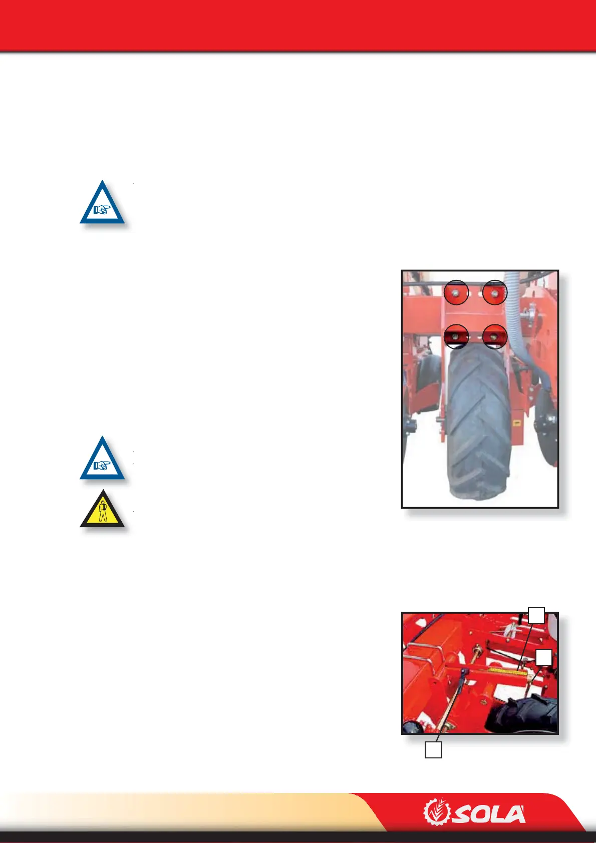
Fig. 6.59
3
2
1
ADJUSTMENTS
6.6 DRIVE WHEELS
There are two types of drive wheels:
- Front drive wheels, which are xed in height (see section 6.6.1).
- Rear drive wheels, which are adjustable in height (see section 6.6.2).
THE DRIVE WHEELS HAVE TO BE ASSEMBLED BETWEEN 2 ROWS. IT IS PREFERABLE THAT THEY
COINCIDE WITH THE TRACTOR’S WHEELS.
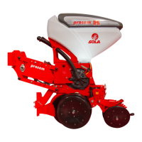
6.6.1 FRONT DRIVE WHEELS, FIXED IN HEIGHT
The position of the drive wheel needs to be adjusted so that
it runs between 2 planting rows. To adjust its position, follow
these steps:
1- Raise the planter until the drive wheels are not in con-
tact with the ground.
2- Loosen the nuts in order to shift the wheel.
3- Place the wheel at the desired position.
4- Tighten strongly the nuts.
IN PLANTERS EQUIPPED WITH FRAME OF TYPE TELESCOPIC,
VARIANT AND VARIANT IDRA, ADJUST THE DRIVE WHEELS
WHEN THE MACHINE IS OPEN.
IN MACHINE VERSIONS TELESCOPIC, VARIANT AND VARIANT
IDRA, PERFORM THE ADJUSTMENTS ONLY WHEN THE TRAC-
TOR’S ENGINE IS OFF AND THE IGNITION KEY HAS BEEN RE-
MOVED.
6.6.2 FRONT DRIVE WHEELS, ADJUSTABLE IN HEIGHT
The position of the drive wheels needs to be adjusted so that each one runs between 2 planting
rows. To adjust their position, follow these steps:
1- Raise the planter until the drive wheels are not in con-
tact with the ground.
2- Loosen the locking lever (1, Fig. 6.59)
3- Turn the crank (2, Fig. 6.59) until the wheel is placed
at the desired height. To adjust the wheel use the gra-
duated scale (3, Fig. 6.59).
4- Lock the wheel’s position using the lever (1, Fig. 6.59).