92
1
2
3
Fig. 6.124
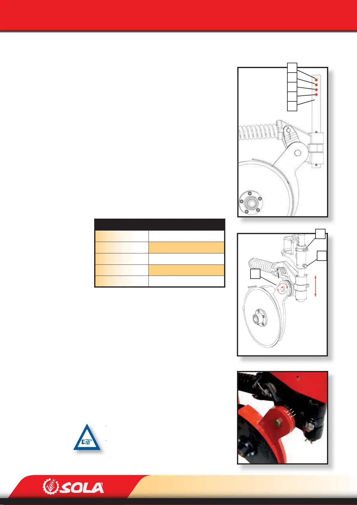
Fig. 6.125
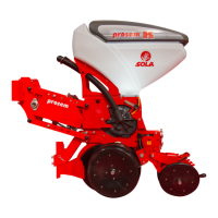
Fig. 6.123
E
D
C
B
A
ADJUSTMENTS
6.18.2 FERTILISER’S DOUBLE DISC
The rod has 4 possible positions placed along 6 cm (Fig.
6.123). To adjust rod’s height:
ROD’S HEIGHT
The rod has 4 possible positions placed along 6 cm
(Fig. 6.123). To adjust rod’s height:
1- Remove the pin (1, Fig. 6.124)
2- Loosen the screw (2, Fig. 6.124)
3- Shift the rod to the desired position.
4- Place the pin in the desired hole to x the posi-
tion (1, Fig. 6.124)
5- Finally, lock the rod using the screw and the
lock nut (2, Fig. 6.124).
POSITION OF THE DOUBLE DISC’S CONNECTING ROD
For a more precise adjustment of the fertilizer’s
height, the connecting rod’s angle needs to be
adjusted:
1- Loosen the discs’ xing screw (3, Fig. 6.124)
2- Turn the discs until reaching the desired angle
of the connecting rod.
3- Tighten the xing screw (3, Fig. 6.124).
WHEN ADJUSTING THE CONNECTING ROD’S AN-
GLE, ADJUST THE COG’S TOOTH SPACE SO THAT
THEY STAY AS ALIGNED AS POSSIBLE (Fig. 6.125).
ROD’S POSITION ROD’S DEPTH (cm)
A 0
B 2
C 4
D 6
E * 8
* Not available in versions No-Till of the fertilizer’s disc.