ADJUSTMENTS
9
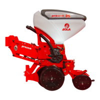
AFTER CHANGING THE POSITION OF THE AD-
JUSTING VALVE, CHECK THE PRESSURE VALUES
USING THE VACUUM GAUGE (FIG. 6.25). IF NE-
CESSARY, ADJUST THE FAN’S TURNING SPEED
TO ADAPT THE PRESSURE VALUES TO THE
ONES IN THE TABLE OF SECTION 6.4 SUCTION
SYSTEM-FAN.
Fig. 6.26
A1
A2
B
1
0
6.12 OPENING COMPONENTS
The depth at which the opening components are buried de-
pends on:
- The planting depth of the metering unit which has
the opening component assembled.
- The opening component’s adjustment.
ADJUST THESE COMPONENTS ONLY AFTER AD-
JUSTING THE METERING UNIT’S PLANTING DEP-
TH.
IN THE CASE OF NO-TILL FARMING, THE TUR-
BO DISC OPENERS NEED TO BE ASSEMBLED ON
THE PLANTER’S FRAME AND NEED TO COIN-
CIDE WITH EACH METERING UNIT’S SOWING
ROW. THE FURROW-OPENER BLADE NEEDS TO
BE ASSEMBLED ON THE METERING UNITS (see
sections 6.12.3 ADJUSTING THE FURROW-OPE-
NER BLADE and 6.14 TURBO DISC OPENER).
6.12.1 ADJUSTING THE BLADE AND THE
CLOD REMOVER
The depth at which the blade and the clod remover are
going to be buried depends on the type of metering unit:
ATTENTION: ADJUST THE BLADE 1 OR 2 CM
BELOW PLANTING DEPTH.
- METERING UNITS K:
1- Loosen the screws (1, Fig. 6.89) to free the blade and the
clod remover.
2- Remove safety ring and securing bolt (2, Fig.6.89).
3- Place the blade and the clod remover at the desired hei-
ght.
4- Tighten the screws (1, Fig. 6.89) to x both components.
1
Fig. 6.89
2
CLOD REMOVERS CAN BE REPLACED BY DISC OPE-
NERS OR FURROW-OPENER BLADES OR FURROW’S
RESIDUE ROTARY CLEANERS.
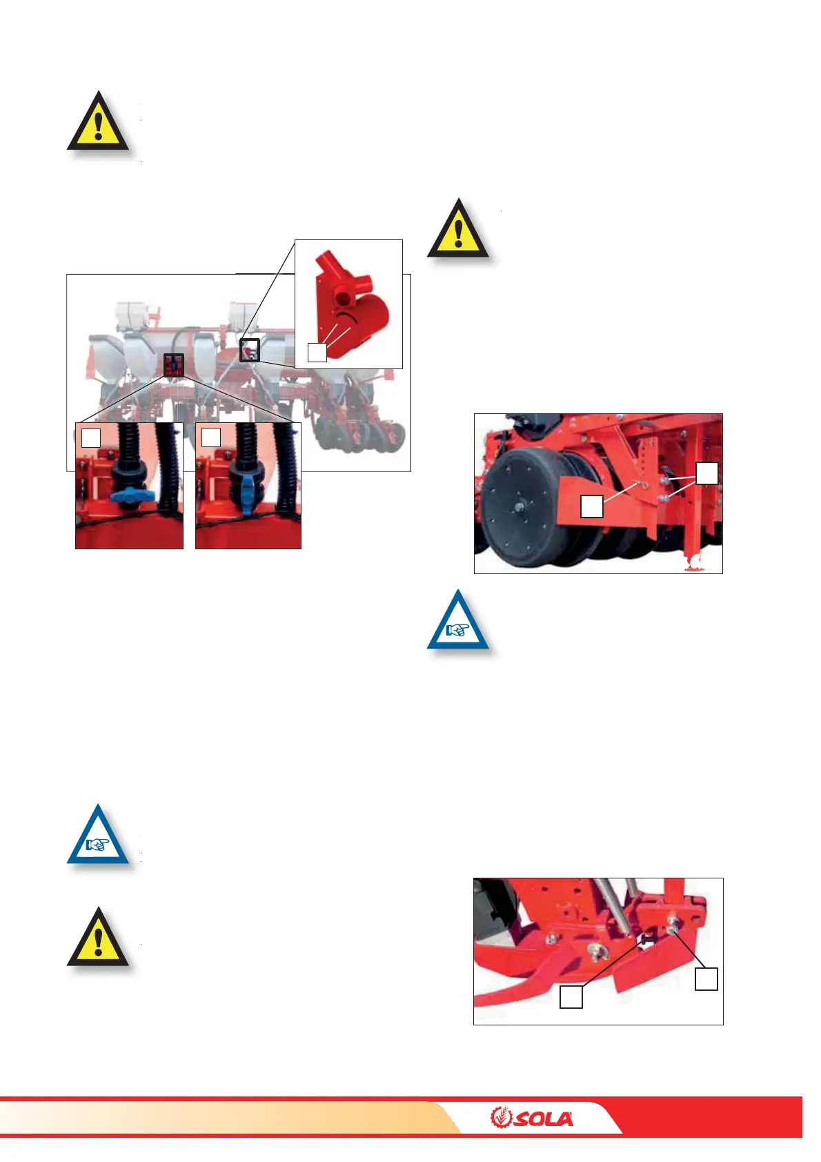
- METERING UNITS P:
1- Loosen the screw (B, Fig. 6.90) to free the blade.
2- Place the blade at the desired depth and x it by tighte-
ning the screw (B, Fig. 6.90).
3- Loosen the screw (C, Fig. 6.90) to free the clod remover.
4- Shift the clod remover along the blade until it reaches the
desired height.
5- Fix the clod remover to the blade by tightening the screw
(C. Fig. 6.90).
B
C
Fig. 6.90