67
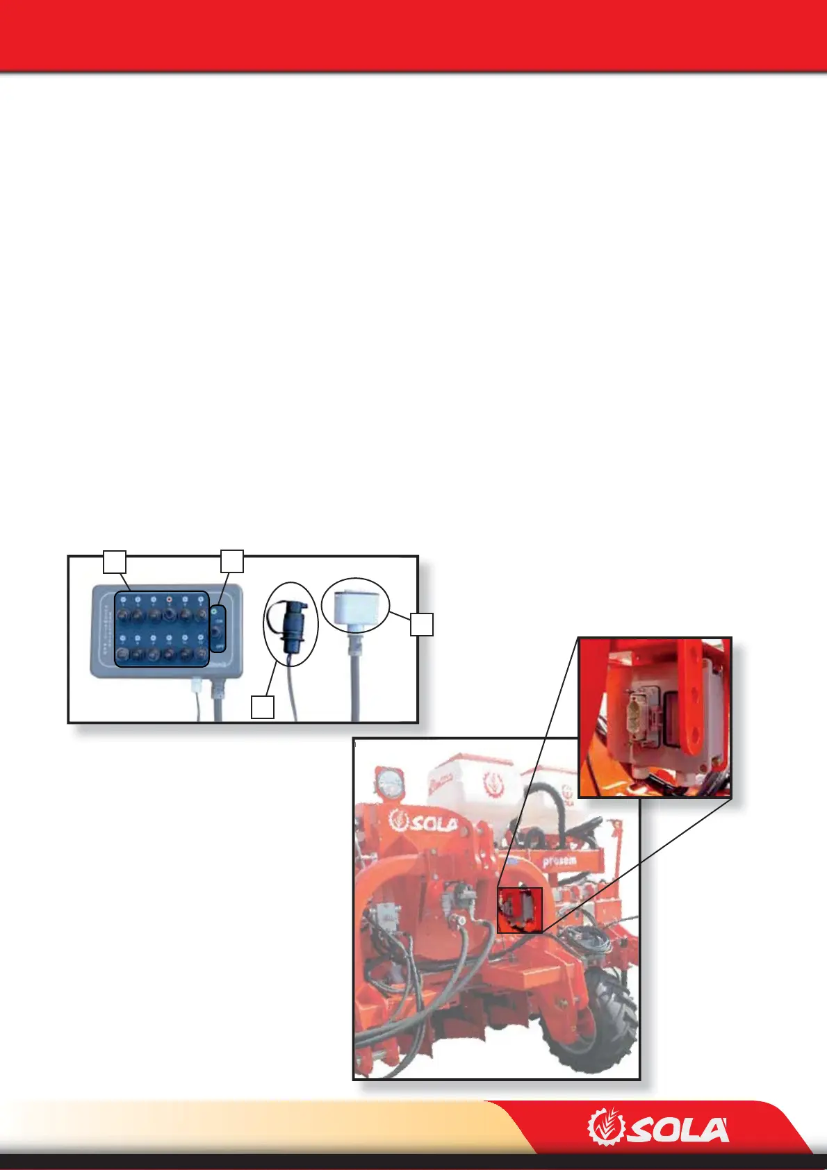
Fig. 6.62
A
B
D
C
Fig. 6.63
ADJUSTMENTS
6.7.2 AUTOMATIC ROW EXCLUSION (OPTIONAL)
Automatic row exclusion is performed using an electronic controller. It contains the following
parts:
- POWER PLUG (A, Fig. 6.62). It needs to be plugged into the tractor’s PTO.
- CONTROLLER’S PLUG (B, FIG. 6.62). It needs to be plugged to the planter’s relay box (Fig.
6.63).
- STARTING SWITCH (C, Fig. 6.62). It has two positions:
ON / OFF
- 12 EXCLUSION SELECTORS for the metering units (D, Fig. 6.62). It has two positions:
EXCLUDE: switch the selector upwards, a red light will appear above the selec-
tor. It indicates that the metering unit has been excluded.
INCLUDE: switch the selector downwards, the red light above the selector will
disappear. This indicates that the unit is starting to plant.