122
B
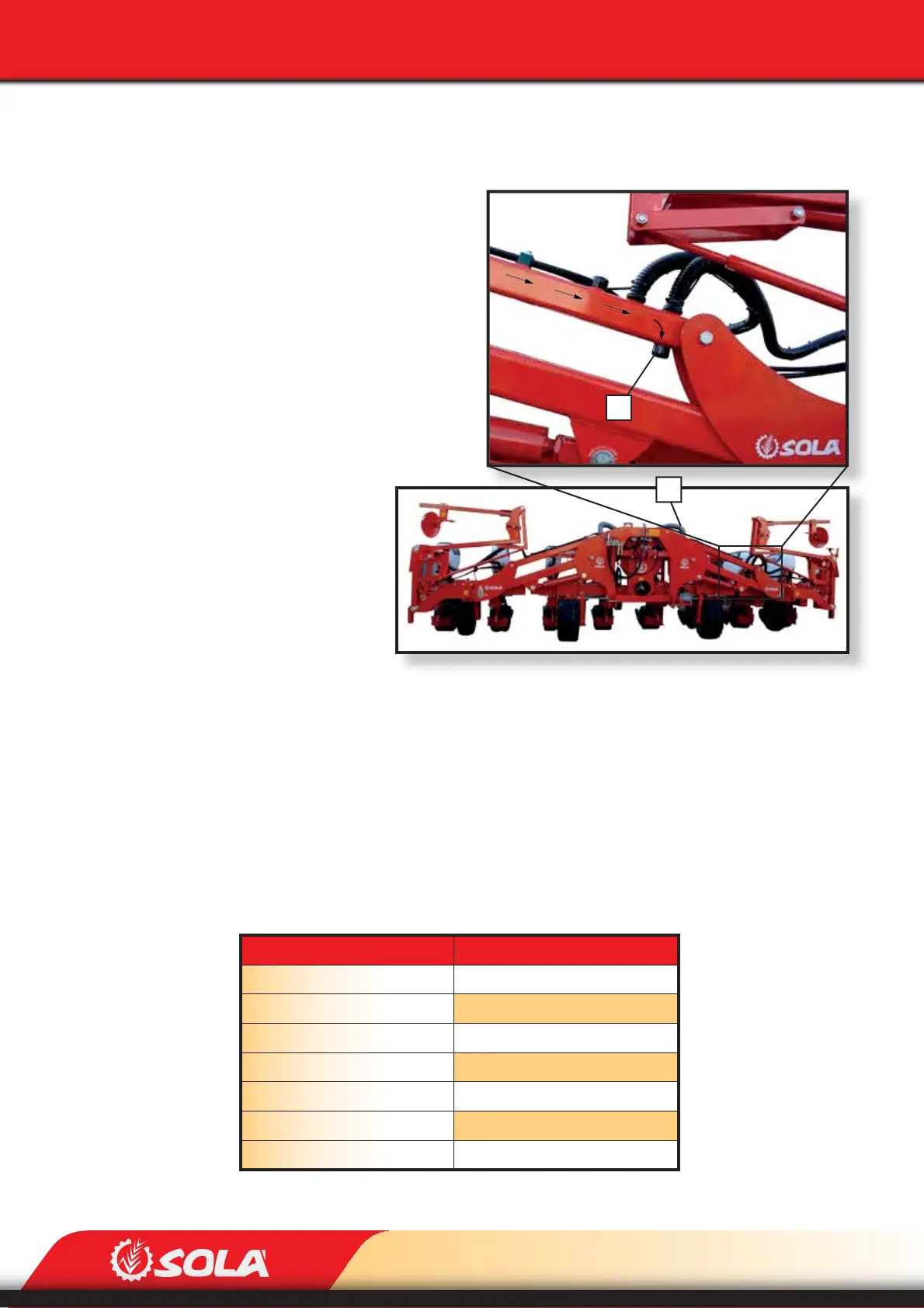
Fig. 9.26
A
MAINTENANCE
TYRE TYPE
AIR PRESSURE (bar)
6,5/80 - 15 4PR 1,5
23x8,50 - 12” 4PR 1,5
23x8,50 - 12” 6PR 2
23x8,50 - 12” 8PR 2,5
23x10,50 - 12” 4PR 1,5
23x10,50 - 12” 8PR 2,5
26x12 - 12” 8PR 2,5
In FOLDING versions of the machine, the air reservoir of the folding parts needs to be cleaned as
well. To perform the cleaning, follow these steps:
1- Remove the suction duct that
connects the main air reservoir
to the folding parts’ air reservoir
(A, Fig. 9.24 or 9.26).
2- R
emove the lower cap of the fol-
ding parts’ air reservoir (B, Fig.
9.26).
3- Use compressed air to blow air
into the folding parts’ air reser-
voir in the direction indicated by
the arrows in Fig. 9.26.
4- Place the lower cap back (B, Fig.
9.26) and connect
the suction duct
(A, Fig. 9.26).
9.7 SCREWS
All the securing screws which x the components to the planter need to be checked and tigh-
tened if necessary after the rst 10 hours of work. Especially check the securing screws of the
metering units, the three-point frame, the wheels and the supports of the track markers.
9.8 TYRE PRESSURE
Before starting working with the planter, check that the tyre pressure is correct.