62
A
B
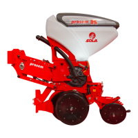
Fig. 6.53
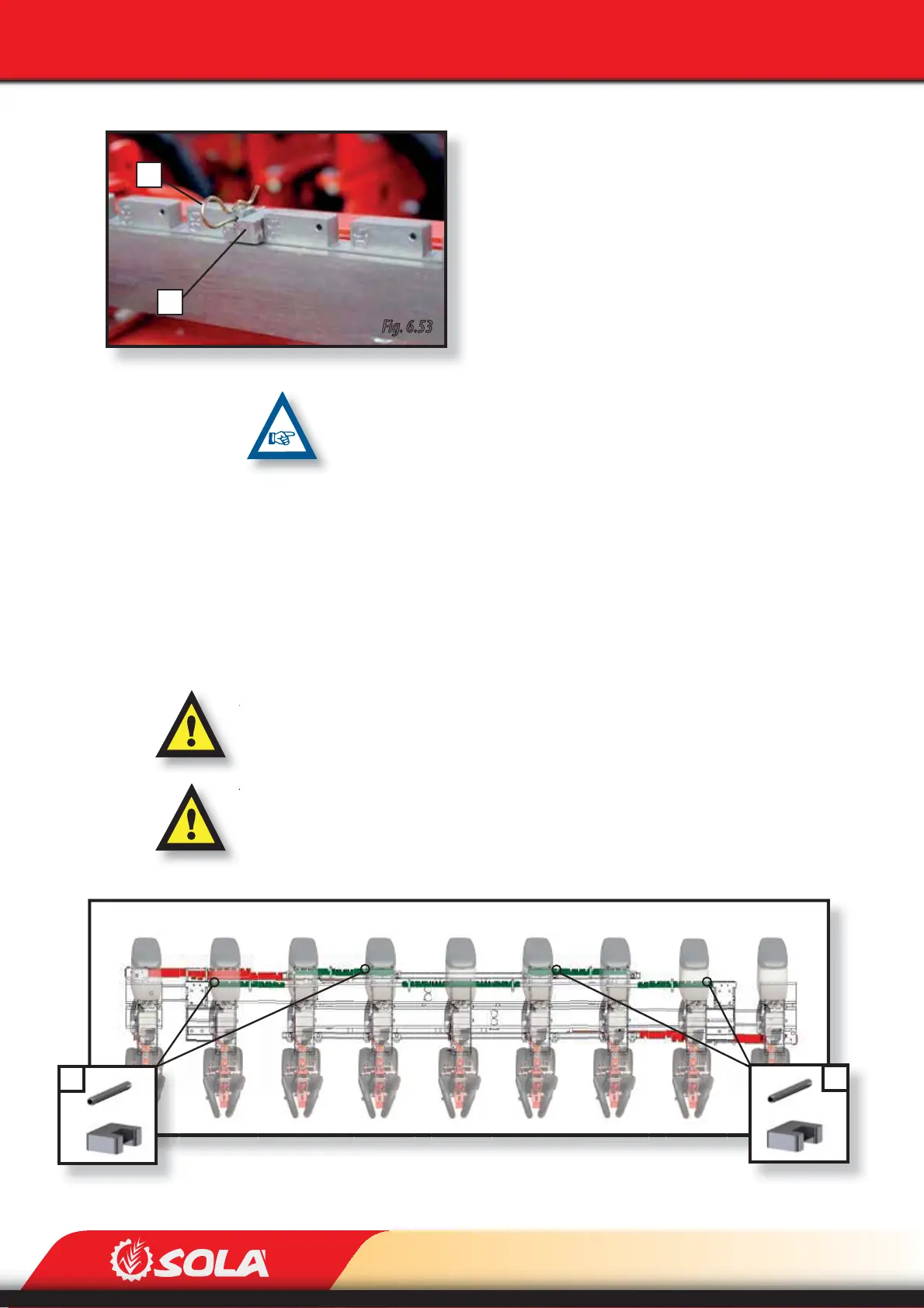
Fig. 6.54
A
A
ADJUSTMENTS
To adjust the row spacing, the 6 row spacing (A, Fig. 6.53)
stops must be placed at the desired spacing marked on the
unit’s slotted bars (red slotted bars Fig. 6.52). To adjust the
row spacing, follow these steps:
1- Remove the pin (B, Fig. 6.53)
2- Remove the aperture stop (A, Fig. 6.53).
3- Place the aperture stop at the desired spacing.
4- Place the pin in the hole to lock the stop.
5- Open the machine using the hydraulic system: the
row spacing will be the selected one.
PLACE ALL THE STOPS AT THE SAME ROW SPACING MARKED ON THE SLOTTED
BARS.
6.5.5.2 IDRA300/9 9F40-55 8F65-75 AND IDRA330/9 9F45-60 8F70-80
This model allows to adjust the spacing between:
- 8 ROWS at 40, 45, 50 and 55 or 9 ROWS at 65, 70 y 75 cm (in frame model IDRA300/9 9F40-
55 8F70-80).
- 8 ROWS at 45, 50, 55 and 60 or 9 ROWS at 70, 75 and 80 cm (in frame model IDRA330/9
9F40-55 8F65-75).
ADJUST THE DISTANCE BETWEEN METERING UNITS ONLY WHEN THE MACHINE IS COMPLETELY
CLOSED, OTHERWISE THE MACHINE COULD BE DAMAGED.
THIS FRAME MODEL HAS SOME FIXED STOPS ASSEMBLED (A, FIG. 6.54). THEY HAVE TO BE PLA-
CED ALWAYS IN THE BARS’ NON-MARKED SLOTS (in GREEN, FIG. 6.54). THEY MUST NEVER BE
REMOVED UNDER ANY CIRCUMSTANCE, OTHERWISE THE MACHINE COULD BE DAMAGED.