30
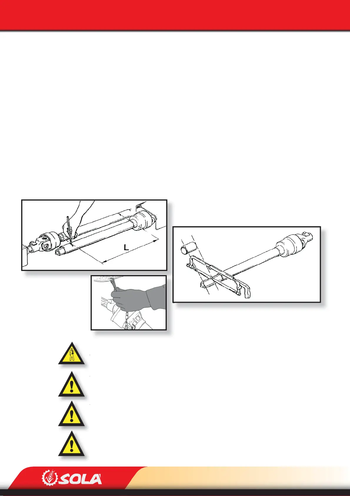
Fig. 5.10
Fig. 5.9
Fig. 5.11
STARTING
5.2 CONNECTING AND ADAPTING THE PTO SHAFT
Once the planter is coupled with the tractor, THE PTO SHAFT SHOULD BE ADAPTED in the
case the planter model is provided with a mechanical fan:
The PTO shaft needs to be dismounted and one of its ends needs to be inserted into the trac-
tor’s universal joint shaft. The other end needs to be inserted into the planter. To perform this,
insert the PTO shaft into the axles of both machines while keeping the safety pin pressed. Then,
release the safety pin and pull the PTO shaft back until you hear “click”. That means that the pin
is in place.
Look for the minimal movement length “L” (g. 5.9) by raising and lowering the hydraulic lift.
Cut the spare plastic and metal into parts of the same length and remount the PTO shaft.
Operate the hydraulic lift and check that the PTO shaft’s movement is correct.
Secure the PTO shaft using the chain (Fig. 5.11).
WHEN OPERATING THE PTO SHAFT CHECK THAT THE ENGINE IS OFF. ALWAYS WORK WITH THE
PTO SHAFT PROTECTED AND IN GOOD CONDITION. PREVENT THE PTO SHAFT’S TUBE FROM
TURNING BY SECURING IT WITH THE CHAIN PROVIDED.
WHEN LOWERING THE PLANTER TO THE GROUND, UNPLUG THE TRACTOR’S UNIVERSAL JOINT
SHAFT SO THAT THE PTO SHAFT DOES NOT HAVE AN EXCESSIVE INCLINATION (MAX. 35º).
WHEN HOLDING THE TRACTOR UNIVERSAL JOINT SHAFT’S CLUTCH IN, PERFORM IT GENTLY.
STARTING SUDDENLY COULD SERIOUSLY DAMAGE THE PLANTER.
IN PLANTERS PROVIDED WITH FRONTAL TRANSPORT TROLLEY AS OPTIONAL EQUIPMENT, A HO-
MOKINETIC PTO SHAFT HAS TO BE COUPLED TO THE TRACTOR’S PTO SHAFT.