63
A
B
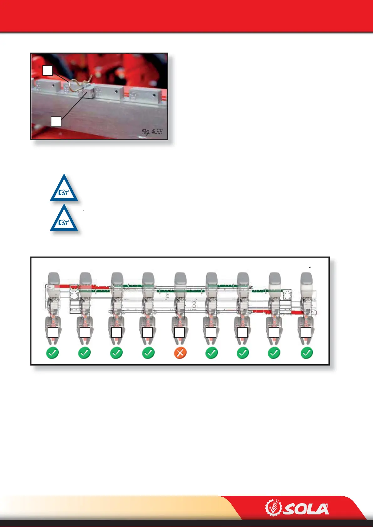
Fig. 6.55
Fig. 6.56
1 2 3 4 5 6 7 8 9
ADJUSTMENTS
To adjust the row spacing, the 6 row spacing (A, Fig. 6.55)
stops must be placed at the desired spacing marked on the
unit’s slotted bars (red slotted bars Fig. 6.52). To adjust the
row spacing, follow these steps:
1- Remove the pin (B, Fig. 6.55).
2- Remove the aperture stop (A, Fig. 6.55).
3- Place the aperture stop at the desired spacing.
4- Place the pin in the hole to lock the stop.
PLACE ALL THE STOPS AT THE SAME ROW SPACING MARKED ON THE SLOTTED BARS.
TO ADJUST THE MACHINE TO 8 ROWS, THE CENTRAL METERING UNIT HAS TO BE EXCLUDED (Fig.
6.56), SEE SECTION 6.7 EXCLUDING A METERING UNIT.