57
ADJUSTMENTS
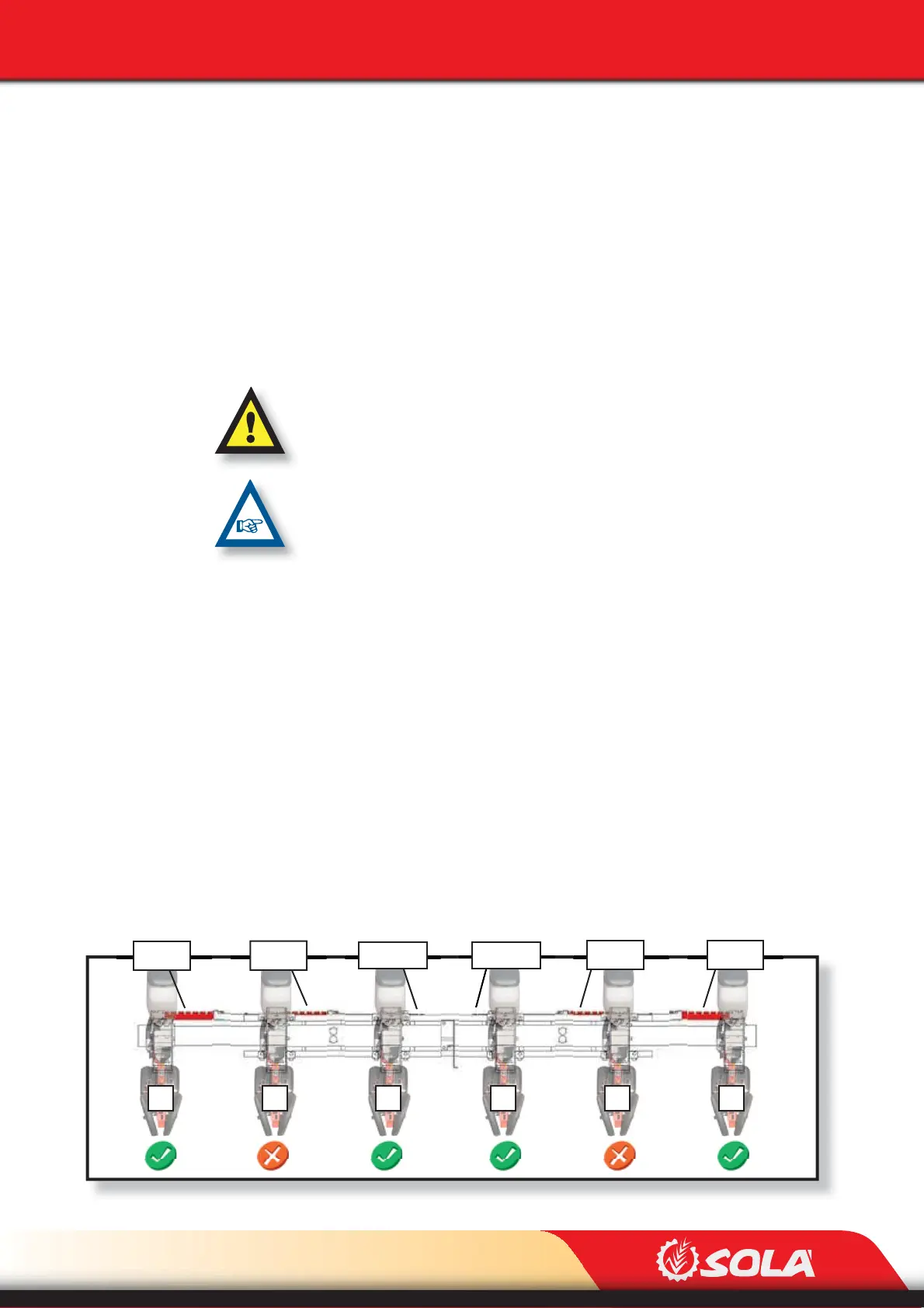
Pos. 50 Pos. 45 Pos. 4F95
Pos. 45 Pos. 50Pos. 4F95
Fig. 6.45
2 3 4 5 6 7
6- Close the machine using the hydraulic system.
7- Place the aperture stops at the desired value (70, 75 or 80).
8- Open the machine using the hydraulic system: the row spacing will be the se-
lected one.
To adjust the machine at 4 ROWS at 95 cm, the following parts are required:
- 6 APERTURE STOPS
TO ADJUST THE MACHINE AT 4 ROWS, THE FOUR SPECIAL STOPS OF 6 ROWS
HAVE TO BE STORED IN THEIR STORAGE PLACE AT THE FRAME’S ENDS. (FIG. 6.43) .
IN CASE THE 6 ROWS SPECIAL STOPS ARE ASSEMBLED IN THE BARS AND CAN
NOT BE REMOVED, OPEN SLIGHTLY THE MACHINE IN ORDER TO BE ABLE TO RE-
MOVE THEM.
To adjust the 4 row spacing:
1- Exclude the units No. 2 and 5 (Fig. 6.45), see section 6.7 EXCLUDING A METE-
RING UNIT.
2- Remove the metering unit’s pins (B, Fig. 6.44) and the aperture stops (A, Fig.
6.44).
3- Place the aperture stops of the units using the pins as indicated below:
- Units 1 and 6 at position 50.
- Units 2 and 5 at position 45.
- Units 3 and 4 at position 4F95 (marked on the slotted bar).
4- Open the machine using the hydraulic system: the row spacing will be the se-
lected one.