59
ADJUSTMENTS
To adjust the machine at 6 ROWS at 70, 75 or 80, the required parts are:
- 6 TOPES DE APERTURA
- 4 TOPES ESPECIALES DE 6 FILAS
THE 6 ROW STOPS CAN BE STORED AT THE FRAME’S ENDS, IN THEIR STORAGE
PLACE AT THE FRAME’S ENDS. (FIG. 6.48)
IN CASE THE APERTURE STOPS ARE ASSEMBLED IN THE BARS, THE ADJUSTMENT
SHOULD BE PERFORMED FROM STEP 7 ON.
To adjust the 6 row spacing:
1- Exclude the central unit (Fig. 6.49), see section 6.7 EXCLUDING A METERING
UNIT.
2- Remove the metering unit’s pins (B, Fig. 6.47) and the aperture stops (A, Fig.
6.47).
3- Place the aperture stops of the units at the position indicated in Fig. 6.49:
4- Place the pins in the holes to lock the stop.
5- Open the machine using the hydraulic system.
6- T
ake the four special stops of 6 rows placed at the frame’s ends and place them at
position 45 for the units No. 1, 2, 5 and 6 (the machine should be open to do this).
7- Close the machine using the hydraulic system.
8- Place the aperture stops of the units at the desired spacing (70, 75 or 80).
9- Open the machine using the hydraulic system: the row spacing will be the se-
lected one.
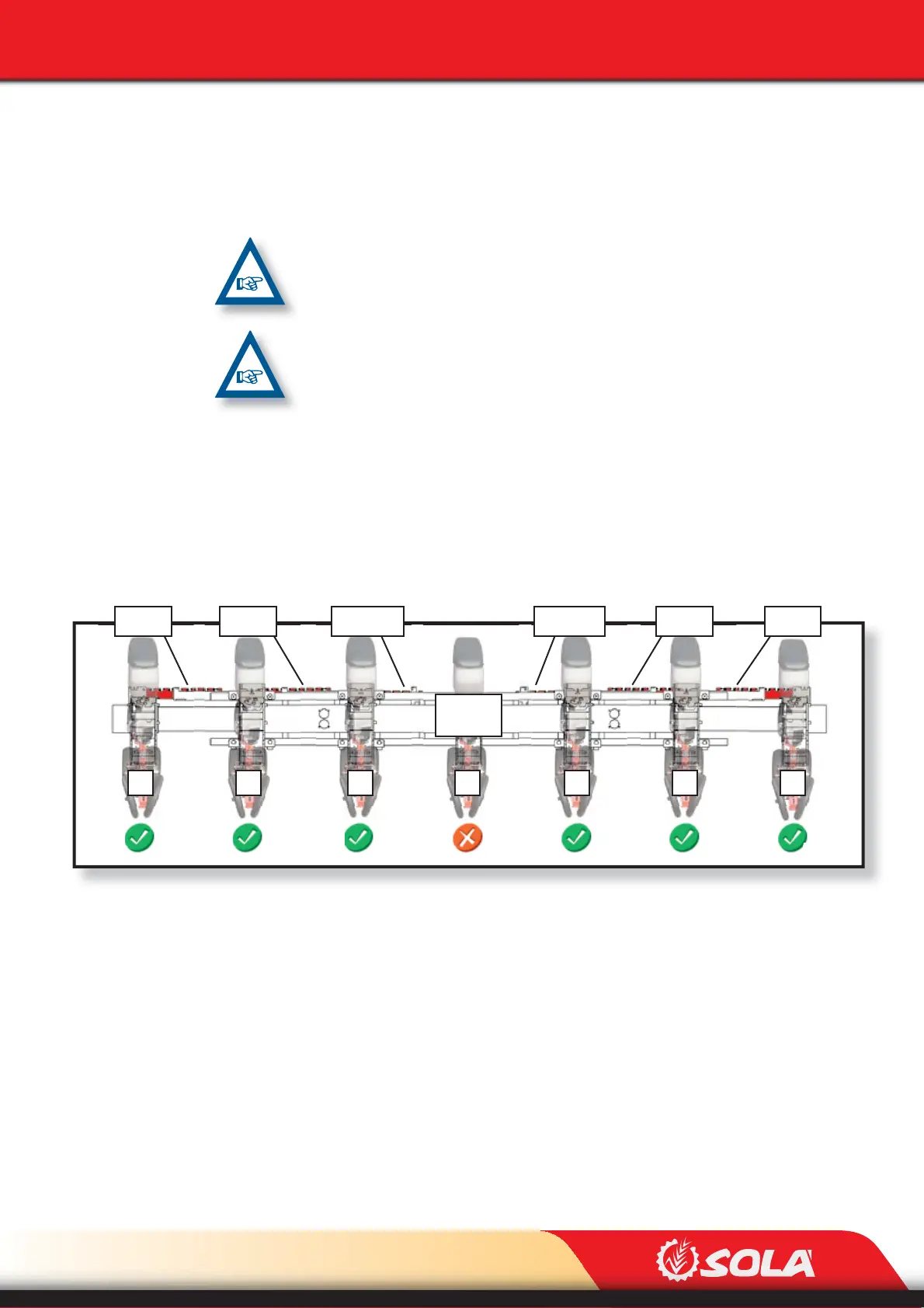
1
1 2 3 4 5 6 7
FIXED
unit
Pos. 70 Pos. 70 Pos. 70Pos. 70Pos. 6x70 Pos. 6x70
Fig. 6.49