87
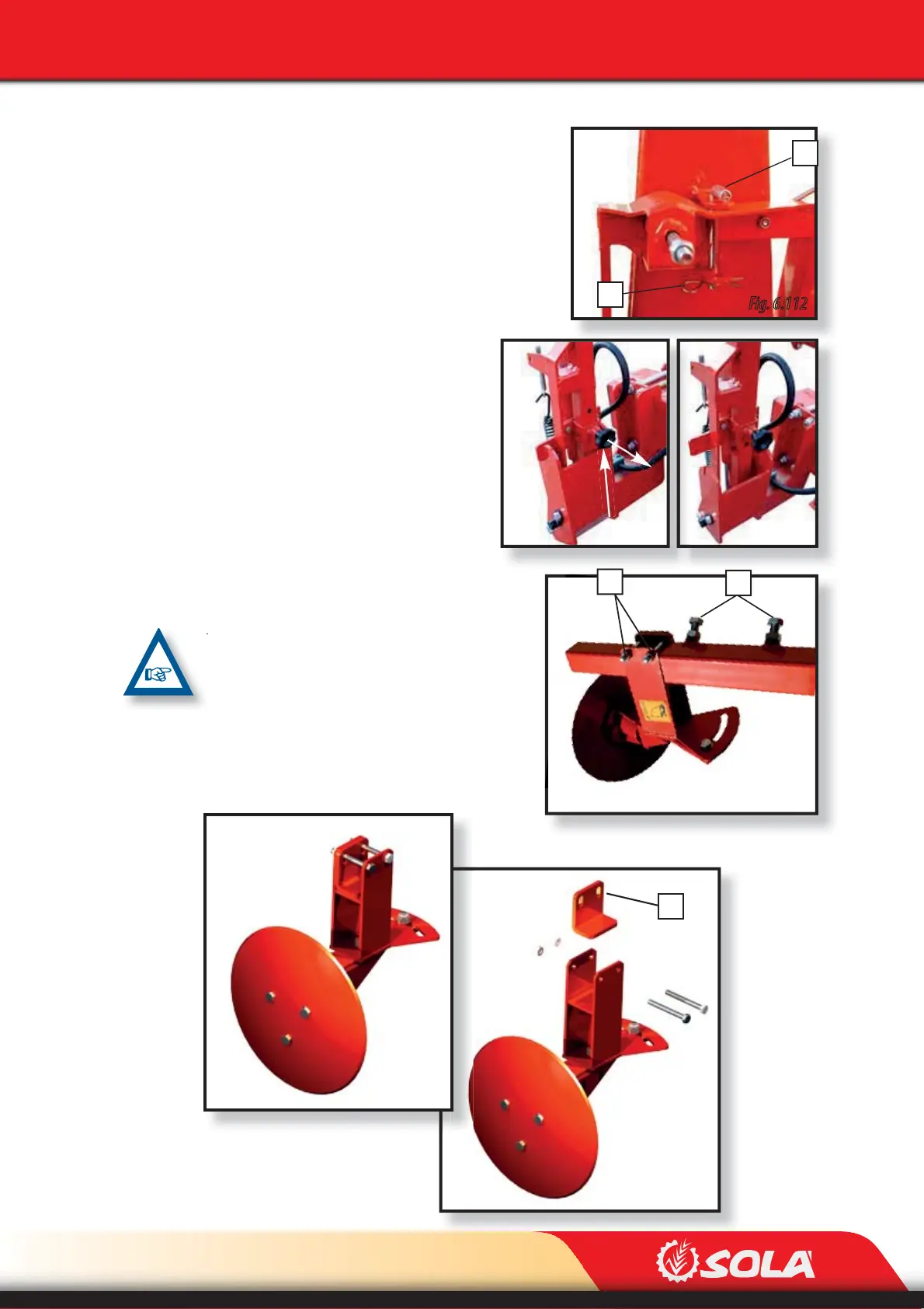
Fig. 6.112
1
2
3
Fig. 6.115
4
Fig. 6.114
Fig. 6.117
A
Fig. 6.116
Fig. 6.113
ADJUSTMENTS
Once the distance B has been calculated, the length of
the track marker’s support can be adjusted:
1- Pressurize the track marker’s hydraulic circuit to
fold them so the locking handle can be removed.
2- Depending on the type of track marker assembled
in the machine, it needs to be unlocked following the-
se steps:
A. Remove the pin (1, Fig. 6.112) and
the locking handle (2, Fig. 6.112).
B. Pull the knob and shift the locking
handle upwards (Fig. 6.113) until it
3- Lower the track marker hydraulically.
4- Loosen the securing nuts (3, Fig. 6.115).
5- Place the track disc at the distance B pre-
viously calculated.
6- Retighten the securing nuts.
TRACK MARKERS CAN BE ADAPTED TO BOTH THE
NARROW TUBE AND THE WIDE TUBE OF THE TE-
LESCOPE. THE ADAPTER FOR THE TUBES (A, FIG.
6.117) HAS TO BE ASSEMBLED IN ORDER TO AD-
JUST THE NARROW SECTION OF THE TUBE. IT
NEEDS TO BE REMOVED TO ADJUST THE WIDE
SECTION OF THE TUBE.