H6 Hybrid Inverter - Installation & Operation Guide
114
Copyright 2017 SolarCity Corporation. All rights reserved.
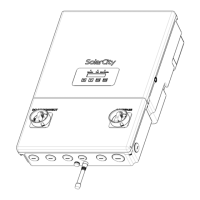
The numbered callouts in
Figure 10-3
correspond to the following:
• Fuse cover (1): Each of the two fuses is protected by a fuse cover. For clarity, only one of
the two fuse covers is shown.
• Fuses (2): The SolarCity H6 inverter uses two fuses. See
“Fuses” on page 66
for the
correct type of fuses to use.
• Fan connector (3): The fan power cable connects to the inverter here.
• Fan screws (4): These Torx head screws hold the fan in place.
• Fan (5): Removing the Torx head screws (#4) allows you to remove the fan assembly.
• PLC Transmitter (6): If the PLC Transmitter is a separate box and not integrated with the
inverter, it can be replaced. See
“PLC Transmitter” on page 116
for PLC replacement
instructions.
• Circuit board cover (7): Removing the six (6) Torx head screws allows you to access the
ZigBee chip.