31
Copyright 2017 SolarCity Corporation. All rights reserved.
Chapter 1 - Welcome
3.5.2 - Battery Pack Interface
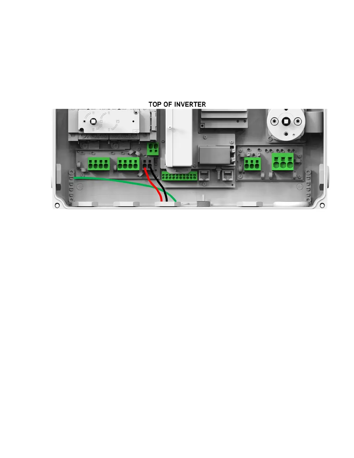
The SolarCity H6 inverter connects directly to the battery pack output via two high-voltage
lines (BATT+ and BATT-). The battery pack is an un-grounded/floating system, meaning that
there must also be a ground connection between the battery pack chassis and the inverter
(bonding bushing not required).
Figure 3-17
displays the battery pack connection to the
inverter.
Figure 3-17: High-voltage battery pack connections
3.5.3 - Communications
The SolarCity H6 inverter also includes multiple communication lines for the battery pack
and the fireman switch. Two sets of low-voltage lines enable communications between
battery pack and the inverter.
• Set 1 includes the communication wires that connect to the following Communication
connectors (16-24 AWG; colors may vary):
- 12V AUX
- 12V AUX GND
- Enable/Disable
- CAN_H
- CAN_L
Set 2 includes the 14-22AWG Fireman Switch connectors that may run either through the
same conduit as the AC grid wiring or through a separate 1/2” conduit:
• Fireman +
• Fireman –