63
Copyright 2017 SolarCity Corporation. All rights reserved.
Chapter 1 - Welcome
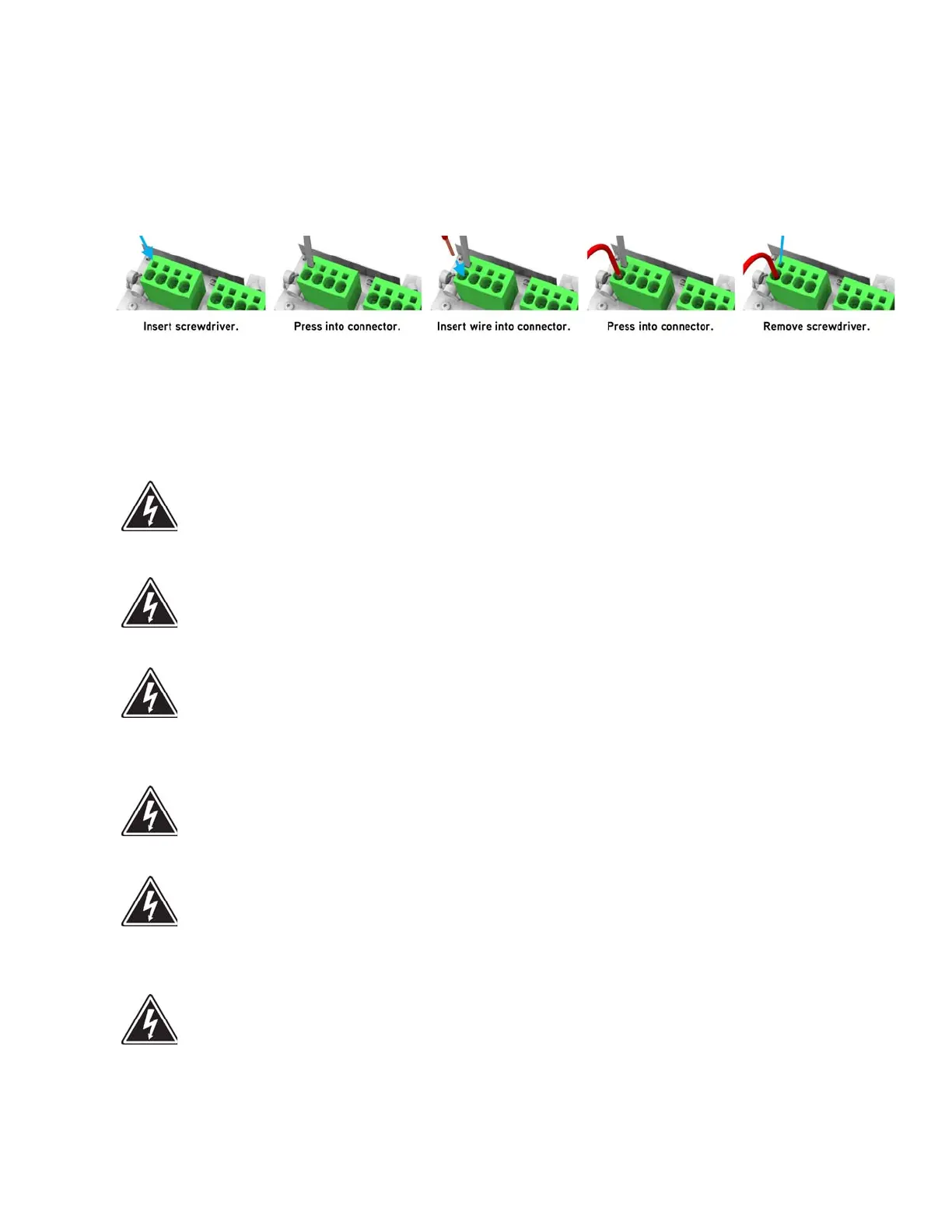
4. See
Figure 5-5
. Connect the wire to the connector as follows:
- To connect a wire, push a 1/8” flat screwdriver into the connector contact on the
spring-clamp connector, and then push the wire into the connector as far as it will go.
Verify that there no strands left out or pushed into another connector.
- To connect a solid wire, simply push the wire into the connector.
Figure 5-5: Using the spring clamp connectors
5.6 - PV Connections
SHOCK HAZARD: PV ARRAYS PRODUCE HAZARDOUS VOLTAGES AND
CURRENTS WHEN EXPOSED TO LIGHT, WHICH CAN CREATE AN
ELECTRICAL SHOCK HAZARD.
SHOCK HAZARD: ENSURE THAT NO LIVE VOLTAGES ARE PRESENT ON ANY
PV INPUT WIRE.
SHOCK HAZARD: ENSURE MAXIMUM PROTECTION AGAINST HAZARDOUS
CONTACT VOLTAGES WHILE ASSEMBLING PHOTOVOLTAIC INSTALLATIONS
BY STRICTLY ISOLATING BOTH THE POSITIVE AND THE NEGATIVE LEADS
FROM ANY GROUNDING.
SHOCK HAZARD: THE DC CONDUCTORS OF THIS PHOTOVOLTAIC SYSTEM
ARE UNGROUNDED AND MAY BE ENERGIZED.
SHOCK HAZARD: THE DC CONDUCTORS OF THIS PHOTOVOLTAIC SYSTEM
ARE UNGROUNDED BUT WILL BECOME INTERMITTENTLY GROUNDED
WITHOUT INDICATION WHEN THE INVERTER MEASURES THE PV ARRAY
ISOLATION.
SHOCK HAZARD: RISK OF ELECTRIC SHOCK AND FIRE. USE ONLY WITH PV
MODULES WITH A MAXIMUM SYSTEM VOLTAGE OF 570V OR LOWER.