H6 Hybrid Inverter - Installation & Operation Guide
4
Copyright 2017 SolarCity Corporation. All rights reserved.
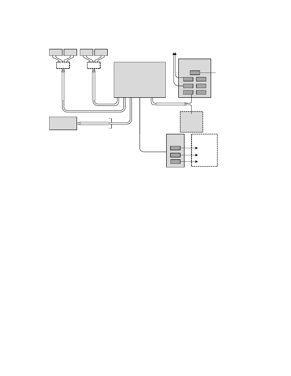
Figure 1-2
depicts a block diagram of a completed SolarCity H6 inverter installation.
Figure 1-2: Block diagram of a complete SolarCity H6 inverter installation
The SolarCity H6 inverter includes various safety features, such as:
• Integrated DC arc-fault circuit interrupter (AFCI) per NEC 2014 690.11 that complies with
UL1699B requirements for Type 1 devices.
• Rapid shutdown (RSD) mechanism per NEC 2014 690.12 is achieved through two parts:
One part is the PLC Transmitter that is located in the H6 inverter, and the other part is the
RSD boxes that are installed under the PV modules within 10’ (3m) of the PV arrays
(depending on the number of strings). This RSD functionality is triggered by either:
- Optional Fireman Switch located beside the main electrical panel, or
- Optional Fireman Switch located under the inverter DC Disconnect Switch.
The Fireman Switch will also safely shut down the battery pack and AC outputs. Refer to
the RSD datasheet and manual for details.
If there is no Fireman Switch, then the RSD mechanism can be initiated using the DC Dis-
connect switch on the SolarCity H6 inverter.
FIREMAN
SWITCH
(optional)
BACKUP
PANEL
refrigerator
microwave
computer
PROTECTED
HOME LOADS
PV2B PV2A PV1B PV1A
RSD RSD
BATTERY
PACK
power
communications
MAIN PANEL/
METER
35A
UTILITY
GRID
NON-PROTECTED
HOME LOADS
SOLARCITY
H6
INVERTER