H6 Hybrid Inverter - Installation & Operation Guide
42
Copyright 2017 SolarCity Corporation. All rights reserved.
3.8 - Fireman Switch and Rapid Shutdown
NEC 690.12 specifies the requirements for a rapid shutdown function that allows the PV
system to be shut down in the event of an emergency in order to prevent shock hazards to
responders and other persons.
3.8.1 - Components
The Rapid Shutdown System (RSS) consists of the following components:
• RSS Box: This is small UL-listed box that is installed on the roof under the PV panel. This
box contains a disconnect that receives signals sent from the PLC Transmitter inside the
SolarCity H6 inverter via the PV power cables. See
“Rapid Shutdown (RSD)” on page 70
and
“SMART Rapid Shutdown Slave” on page 127
.
• PLC Transmitter: This is a small box or PCB with integrated circuit that is installed inside
the SolarCity H6 inverter Wiring Box. This box communicates with the RSS box(es) using
signals sent via the PV power cables. This part is UL-listed as part of the inverter
assembly.
• Fireman Switch: This is an emergency switch that is closed during normal operation.
Activating this switch initiates the rapid shutdown sequence. See
“Fireman Switch” on
page 71
.
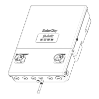
• DC Disconnect Switch: This six-pole switch in the inverter disconnects both the PV array
and battery pack power cables from the internal inverter voltages. See
“DC Disconnect
Switch” on page 25
. This switch also has an auxiliary contact to detect its position.
• Battery Pack Switch: This is a small switch located on the right side of the battery pack
with clearly-indicated ON/OFF positions. Before any commissioning or maintenance
work, this switch must be in the OFF position.
Note: See the battery pack Owner’s Manual for the location of the battery
pack ON/OFF switch.