23
Copyright 2017 SolarCity Corporation. All rights reserved.
Chapter 1 - Welcome
• Additional horizontal mounting holes spaced 2.5” (63.5mm) left and right of center at the
bottom of the Inverter Mounting Bracket are provided for additional bracket and inverter
stability.
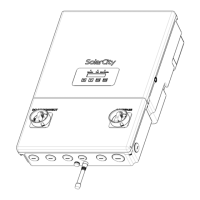
1. The two top hooks slide into back of the SolarCity H6 inverter slots and hold most of the
weight. The two bottom hooks slide into back of the wiring box slots and are useful when
replacing the inverter top section because they hold the wiring box in place.
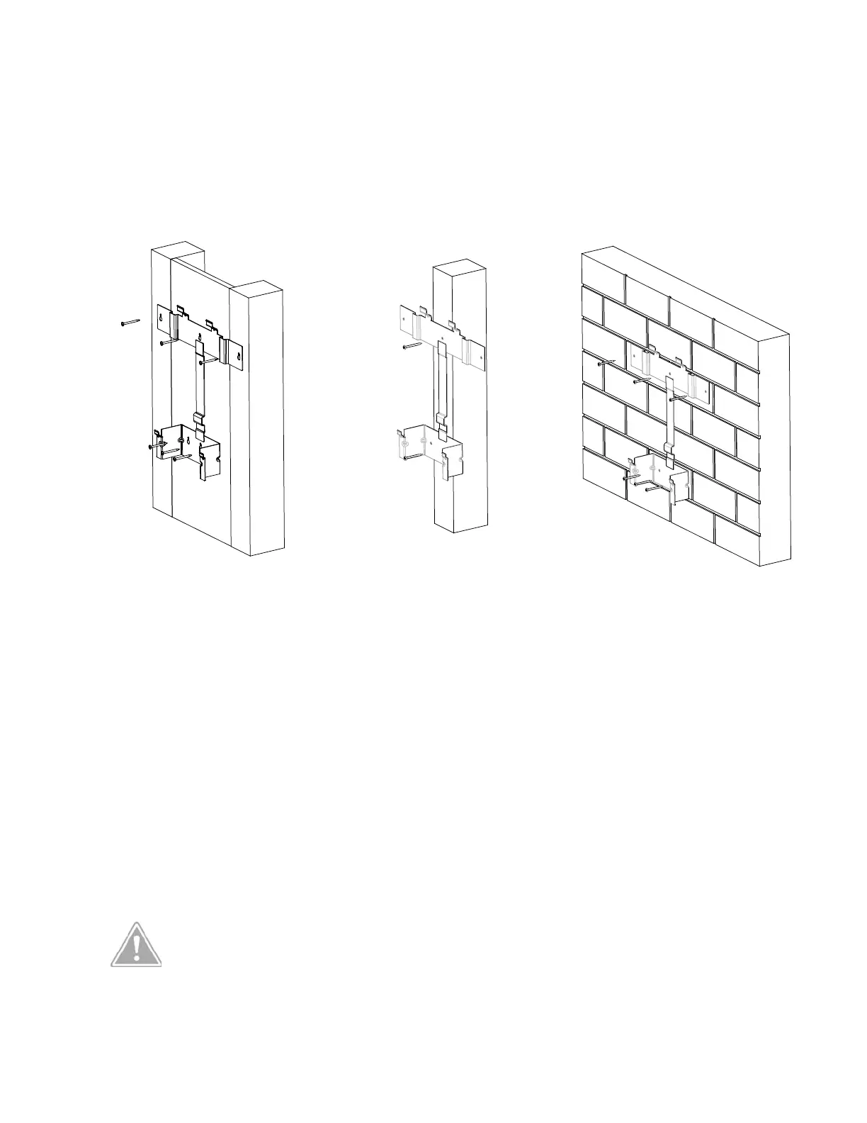
Figure 3-6: Installing the Inverter Mounting Bracket on various wall types
3.3.1 - Standard 16” Wall
When installing the Inverter Mounting Bracket on a standard wall with 16” stud spacing:
• Use one (1) screw in the upper left side into a stud.
• Use one (1) screw in the upper right side into a stud.
• Use one (1) screw with a suitable wall anchor in any of the lower holes (center hole
preferred).
Mount the Inverter Mounting Bracket as described in
“Installing the Inverter Mounting
Bracket” on page 51
.
CAUTION: THE WALL ANCHOR(S) ARE TO BE USED ONLY TO STEADY THE
INVERTER MOUNTING BRACKET AGAINST THE WALL. THEY ARE NOT
INTENDED TO BE WEIGHT BEARING.
16” wood wall 24” wood wall or single pillar masonry/concrete