27
Copyright 2017 SolarCity Corporation. All rights reserved.
Chapter 1 - Welcome
3.5 - Inverter Wiring Box
Do not remove or disturb the connections between the SolarCity H6 inverter top section and
the wiring box, except when replacing the inverter top section. All wiring must be performed
only by qualified personnel.
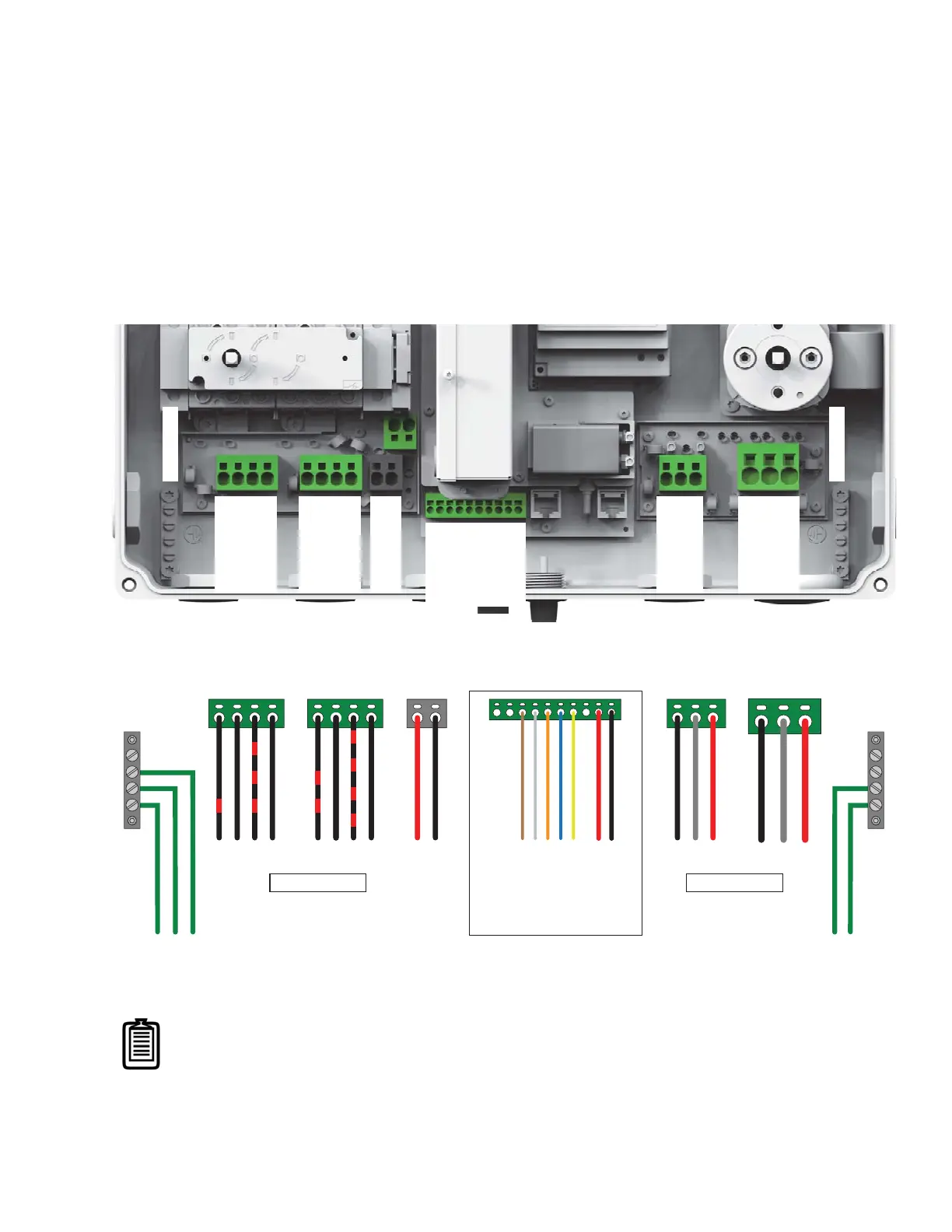
Figure 3-11
shows the SolarCity H6 inverter wiring box
connections. The inside of the wiring box cover also includes a colored label (see
Figure 3-12
)
that depicts the connections. The actual communication wire colors may vary from those
shown on the label.
Figure 3-11: SolarCity H6 inverter wiring box connections
Figure 3-12: Wiring box label
Note: Communication conductor colors may vary from those shown on
the label.
TOP OF INVERTER
PV1A+
PV1A-
PV1B+
PV1B-
GROUND
GROUND
BATT+
BATT-
RESERVED
RESERVED
12V AUX
12V AUX GND
Enable/Disable
CAN_H
CAN_L
RESERVED
Fireman+
Fireman-
BL1
BN
BL2
L1
N
L2
Protected
Home
Loads
AC Grid
Communication
Battery
PV1
PV2A+
PV2A-
PV2B+
PV2B-
PV2
LV WIRE COLOR CODE:
12V+ (LOGIC +) BROWN
GND (LOGIC -) WHITE
ENABLE ORANGE
CN+ (CAN HI) BLUE
CN- (CAN LO) YELLOW
Note: Actual colors may vary.
PV1A (+)
PV1A (-)
PV1B (+)
PV1A (-)
PV2A (+)
PV2A (-)
PV2B (+)
PV2A (-)
BATTERY (+)
BATTERY (-)
12V+ (LOGIC +)
GND (LOGIC -)
ENABLE
CN+ (CAN HI)
CN- (CAN LO)
FIREMAN (+)
FIREMAN (-)
BL1
BN
BL2
L1
N
L2
COPPER WIRE ONLY COPPER WIRE ONLY
GROUND
GROUND